Blog

  • How to Create and Manage a Bucket on Object Storage?

    Introduction

    CMP Object Storage provides scalable storage for files and other unstructured data. It can be used for application data, static website content, online storage, backups, and other workloads that require object-based storage.

    A bucket is a storage container used to organize and manage objects such as files. This guide explains how to create a bucket from the CMP Dashboard, upload files, create and remove folders, delete a bucket, and enable S3 access by generating access credentials.

    Prerequisites

    Before managing Object Storage, ensure that:

    • You have access to the CMP Dashboard.
    • Object Storage is available for your account.
    • You have the required permissions to manage Object Storage resources.
    • For S3-based access, S3 access must be enabled and an access key pair must be generated.

    Note: S3 access credentials consist of an Access Key ID and a Secret Access Key. Treat the Secret Access Key as sensitive information and do not share it publicly.

    Create a Bucket

    A bucket is a container used to store and organize objects in Object Storage.

    Step 1: Log in to the CMP Dashboard

    Log in to your CMP Dashboard using your account credentials.

    Step 2: Open Object Storage

    Navigate to Object Storage from the CMP Dashboard.

    Select Create Bucket.
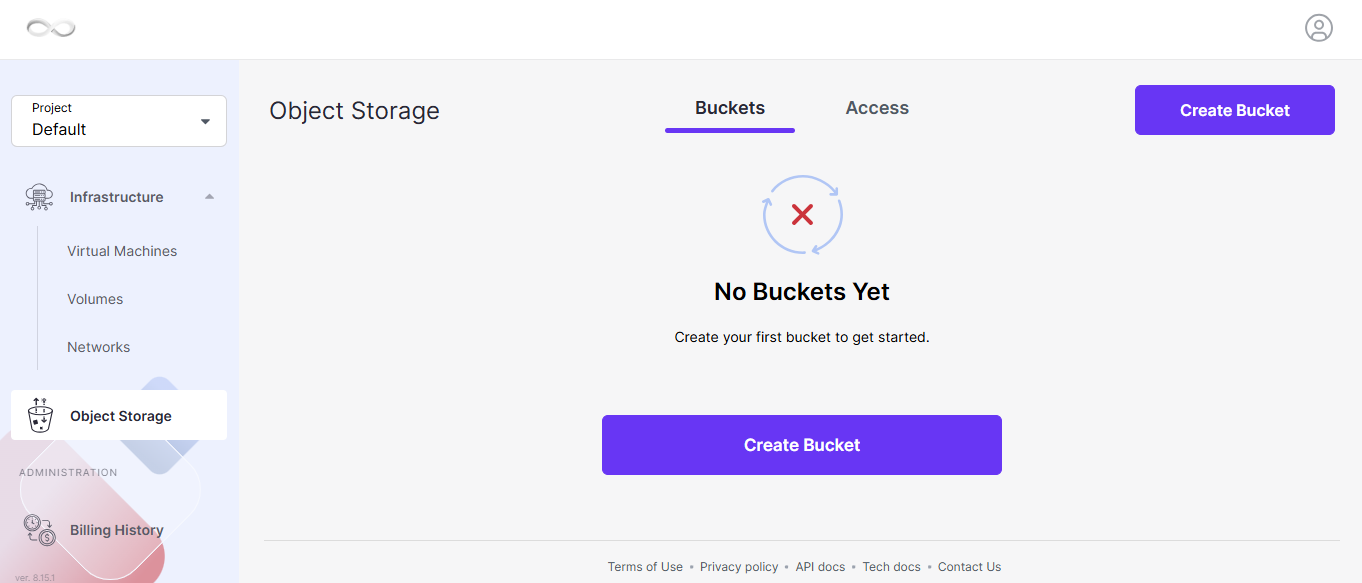
    Create Bucket


    Step 3: Enter the Bucket Name

    Enter a unique name for the bucket.

    If you want the bucket to be publicly accessible, enable the Public Access option.

    Important: Enable public access only when the objects stored in the bucket are intended to be publicly accessible.

    Step 4: Create the Bucket

    After entering the required details, select Create Bucket.
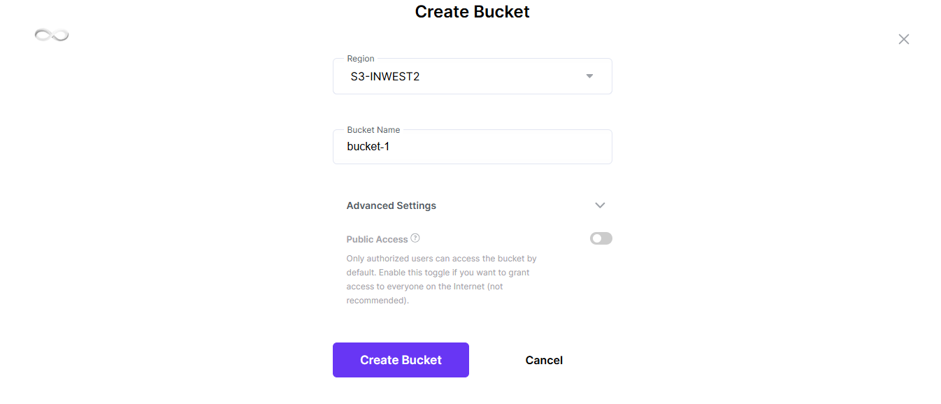
    Create Bucket window

    Once the bucket is successfully created, it will appear in the Object Storage bucket list.

    Upload Files to a Bucket

    After creating a bucket, you can upload files from your local machine.

    Step 1: Open the Bucket

    Navigate to Object Storage and select the bucket where you want to store the files.


    Step 2: Upload Files

    Use the upload option to select files from your local machine.

    Select the required file and complete the upload.
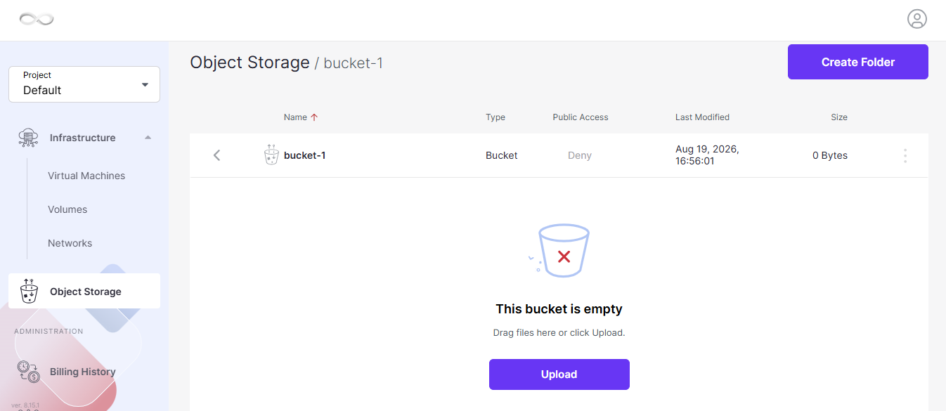
     

    upload option

    After the upload is completed, the file will appear in the bucket.

    Note: The uploaded file is stored as an object inside the selected bucket.

    Create a Folder

    Folders can be created within a bucket to organize objects.

    Step 1: Open the Required Bucket

    Navigate to:

    Object Storage → Bucket

    Open the bucket where you want to create the folder.

    Step 2: Create the Folder

    Select Create Folder.

    Enter the required folder name and create the folder.
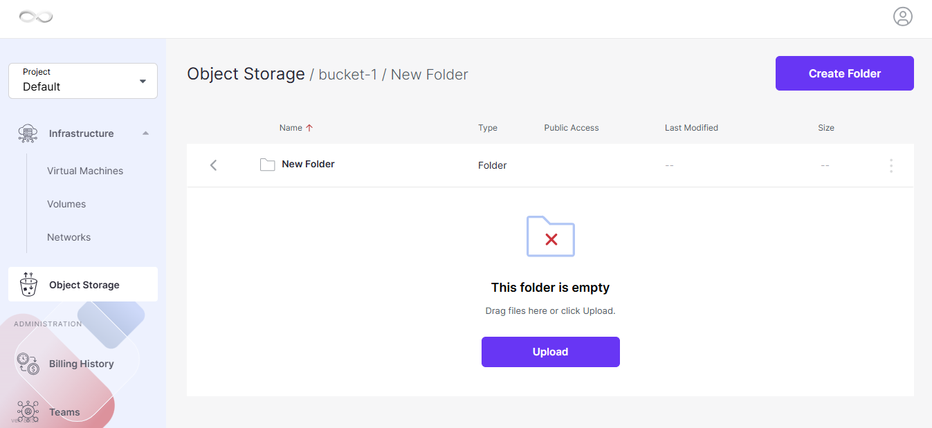
    Create Folder option

    The newly created folder will appear inside the bucket.

    You can then upload files into the folder to organize your objects.

    Remove a Folder

    If a folder is no longer required, it can be removed from the bucket.

    Step 1: Select the Folder

    Open the required bucket and select the folder that you want to remove.

    Step 2: Remove the Folder

    Select Remove to delete the folder.
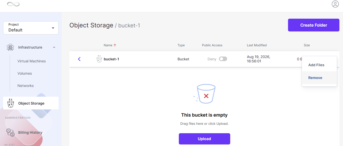
    Remove option

    Important: Verify that you are removing the correct folder before confirming the operation.

    Remove a Bucket

    A bucket can be removed when it is no longer required.

    Step 1: Select the Bucket

    Navigate to the Object Storage bucket list and select the bucket that you want to remove.

    Step 2: Remove the Bucket

    Select Remove and confirm the deletion.
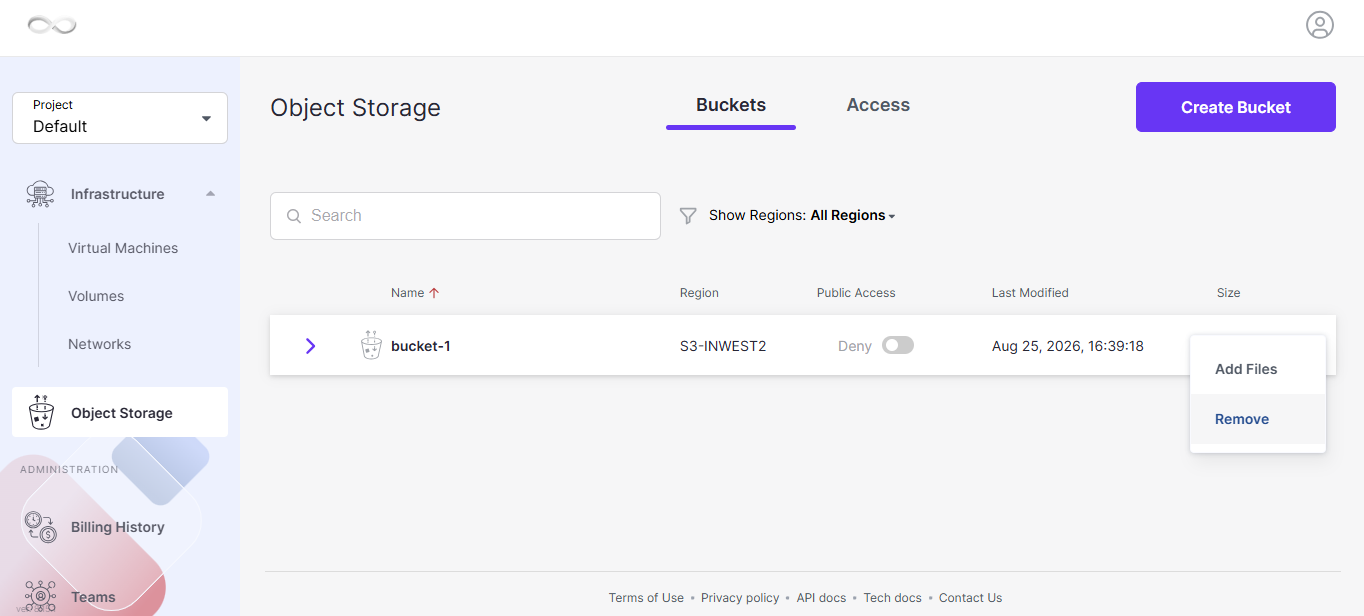
    Bucket actions

    Warning: Make sure that the bucket is no longer required before deleting it. Bucket deletion can remove the storage container and its associated data.

    Enable Access to S3 Storage

    CMP Object Storage provides S3-compatible access. To manage S3 resources programmatically or through S3-compatible tools, you need an S3 access key pair.

    The access key pair consists of:

    • Access Key ID
    • Secret Access Key

    The Access Key ID can be considered the identifier used for authentication, while the Secret Access Key is the corresponding secret credential.

    Step 1: Open Object Storage Access Settings

    Navigate to Object Storage in the CMP Dashboard.

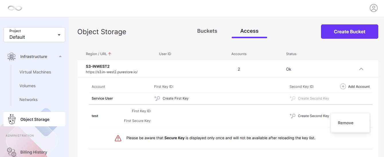
    Open the Access tab.
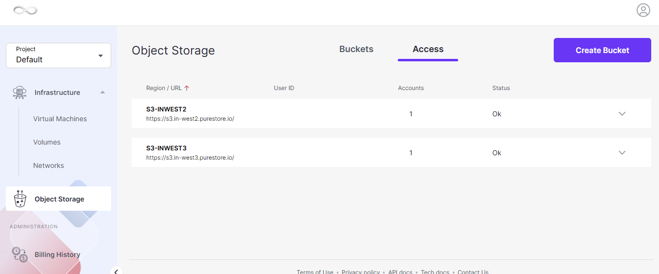
    Access tab

    Step 2: Add an S3 User

    Expand the available options using the dropdown arrow.

    Select + Add Account to create a new S3 user.

    The system automatically generates an access key pair:

    1. Access Key ID
    2. Secret Access Key

    Add Account

    Step 3: Copy the Access Credentials

    Use the copy icon next to the corresponding credential to copy:

    • Access Key ID
    • Secret Access Key

    Security Note: Store the Secret Access Key securely.

    Delete an S3 Access Key Pair

    If an S3 access key is no longer required, it can be removed from the Object Storage access settings.

    Step 1: Open the Access Tab

    Navigate to:

    Object Storage → Access

    Locate the S3 Access Keys section.

    Step 2: Delete the Access Key

    Select the Delete icon next to the access key that you want to remove.

    Confirm the operation by selecting Delete.

    Important: Applications or tools using the deleted access key will no longer be able to authenticate using that credential.

    Remove an S3 User

    An S3 user can be permanently removed from the Object Storage access settings.

    Step 1: Select the User

    Open the Access section.

    Locate the required S3 user and select the ellipsis (…) icon next to the user.

    Step 2: Remove the User

    Select Remove and confirm the operation.

    The selected user will be permanently removed.

    Troubleshooting

    Bucket Creation Is Not Available

    If you cannot create a bucket:

    1. Confirm that Object Storage is available for your account.
    2. Verify that you are logged in to the correct CMP account.
    3. Confirm that you have the required permissions.
    4. Refresh the Object Storage page and try again.

    The Bucket Is Not Visible

    If a newly created bucket does not appear in the bucket list:

    1. Refresh the Object Storage page.
    2. Confirm that the bucket creation operation completed successfully.
    3. Verify that you are viewing the correct Object Storage account or project.

    S3 Access Is Not Working

    If an application or S3-compatible tool cannot access the bucket:

    1. Confirm that S3 access has been enabled.
    2. Verify the Access Key ID.
    3. Verify the Secret Access Key.
    4. Confirm that the credentials have not been deleted.
    5. Generate a new access key if the existing credentials are no longer available.

    For S3-compatible application integration, refer to the relevant CMP Object Storage integration documentation.

    An S3 Access Key Is No Longer Required

    If an access key is no longer being used, remove it from:

    Object Storage → Access → S3 Access Keys

    Removing unused credentials helps maintain controlled access to Object Storage.

    Important Notes

    • Bucket names should be unique.
    • Public access should only be enabled when public access is required.
    • Keep S3 Secret Access Keys confidential.
    • Do not share access credentials with unauthorized users.
    • Verify the bucket before removing it.
    • Verify the S3 user or access key before deleting it.
    • Applications using a deleted access key will lose access through that credential.
    • CMP Object Storage supports S3-compatible access for integration with S3-compatible tools and applications.

    Conclusion

    CMP Object Storage allows you to create and manage buckets for storing files and other objects. From the CMP Dashboard, you can create buckets, upload files, organize objects using folders, and remove resources that are no longer required.

    For S3-compatible access, you can also create S3 users and generate an Access Key ID and Secret Access Key. Always protect these credentials and remove unused access keys to maintain secure access to your Object Storage resources.

    FAQ’s

    What is a bucket in Object Storage?

    A bucket is a storage container used to store and organize objects such as files in Object Storage.

    How do I create a bucket in CMP Object Storage?

    Log in to the CMP Dashboard, navigate to Object Storage, select Create Bucket, enter a unique bucket name, and select Create Bucket.

    Can I upload files directly to a bucket?

    Yes. After creating a bucket, you can open it and upload files from your local machine.

    Can I create folders inside a bucket?

    Yes. Open the required bucket and select Create Folder to organize files into folders.

    Can I make a bucket publicly accessible?

    Yes. Public access can be enabled when creating the bucket using the Public Access option.

    Warning: Enable public access only when the stored objects are intended to be publicly accessible.

    How do I get S3 access credentials?

    Navigate to Object Storage → Access, add an S3 account using + Add Account, and the system will generate an Access Key ID and Secret Access Key.

    Can I delete an S3 access key?

    Yes. Navigate to Object Storage → Access → S3 Access Keys, select the Delete icon for the required key, and confirm the deletion.

    Can I remove an S3 user?

    Yes. From the Access section, select the ellipsis (…) icon next to the user and select Remove.
  • How to Manage Newly Added Disks on a Windows VM?

    Introduction

    When a new disk is attached to a Windows virtual machine, Windows may detect the disk but display it as Offline or Not Initialized. Before the new storage can be used, the disk may need to be brought online, initialized, and configured with a new volume.

    This guide explains how to manage newly added disks on a Windows VM using the built-in Disk Management utility. It covers checking the disk status, bringing an offline disk online, initializing the disk using the GPT partition style, creating a new simple volume, assigning a drive letter, formatting the volume, and verifying that the new storage is available in File Explorer.

    Check the Disk Status

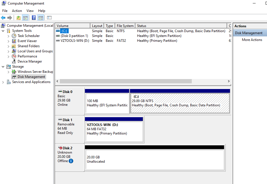
    Windows Disk Management displays whether a disk is Online and available or Offline.

    Newly discovered disks are generally brought online automatically with read/write access. However, a newly attached disk may sometimes be displayed as Offline because of a Windows disk policy.

    Step 1: Open Computer Management

    1. Search for Computer Management from the Windows taskbar.
    2. Open Computer Management.

    Step 2: Open Disk Management

    Navigate to:

    Storage > Disk Management

    Disk Management displays the disks connected to the Windows VM and their current status.

    Windows Disk Management

    Note: Check the disk number and status carefully before performing any disk operation.

    Bring an Offline Disk Online

    If the newly attached disk is displayed as Offline, it must be brought online before it can be initialized or used to create a volume.

    An offline disk may display a message similar to:

    The disk is offline because of a policy set by an administrator.

    Step 1: Select the Offline Disk

    In Disk Management, locate the newly attached disk.

    For example:

    Disk 2 — Offline

    Step 2: Bring the Disk Online

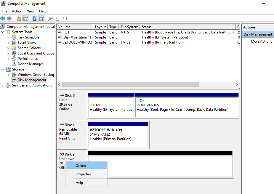
    1. Right-click the disk name, such as Disk 2.
    2. Select Online.

    The disk will become available for further configuration.

    Disk Management showing the Online option

    Important: Make sure you select the newly attached disk. Do not bring an existing production disk online or modify it unless you have confirmed that it is the intended disk.

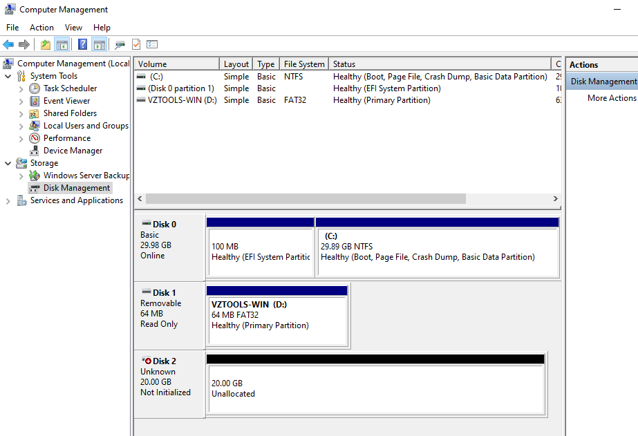
    After the disk is brought online, it may appear as:

    • Not Initialized
    • Unallocated

    Not Initialized and Unallocated

    Initialize the New Disk

    A newly attached disk may need to be initialized before a volume can be created.

    Step 1: Open Initialize Disk

    In Disk Management:

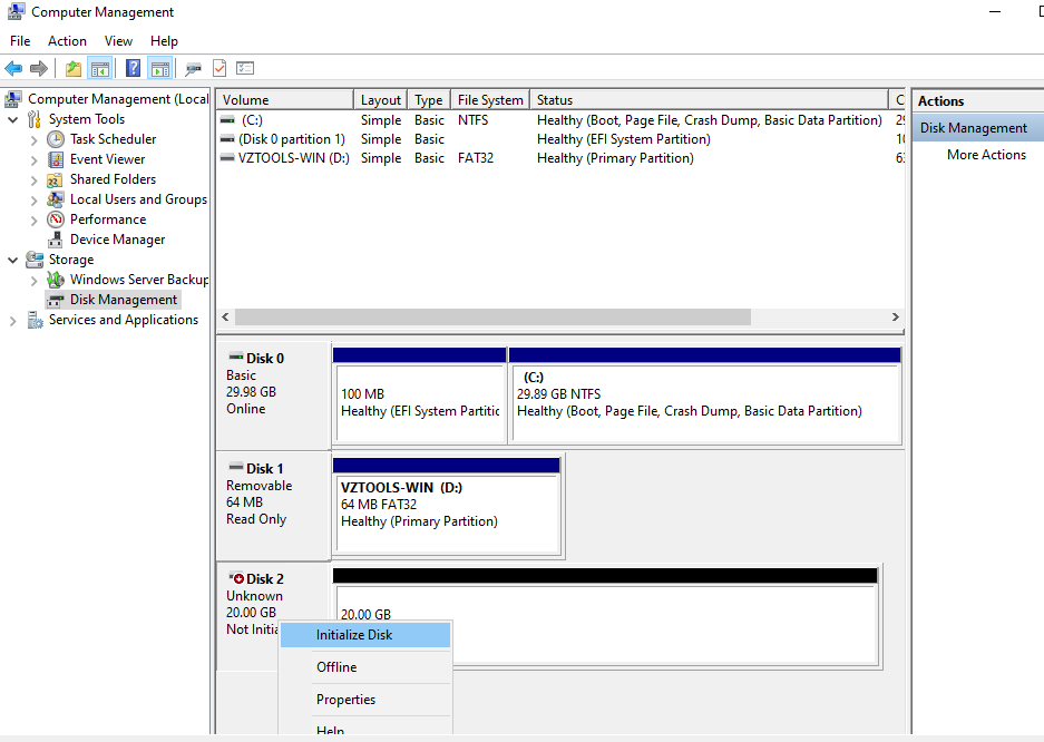
    1. Right-click the disk that you want to initialize.
    2. Select Initialize Disk.

    If the disk is still Offline, right-click the disk first and select Online.

    Initialize Disk option

    Step 2: Select the Partition Style

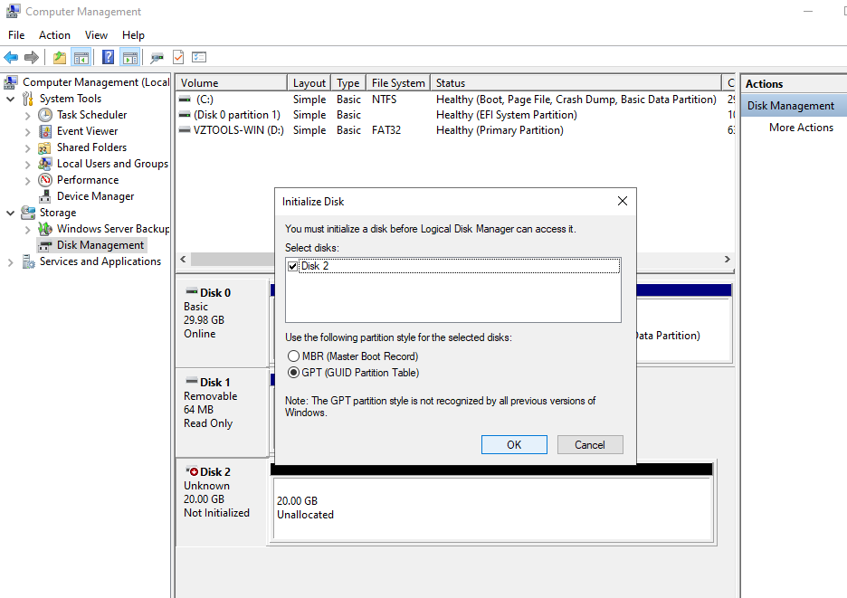
    In the Initialize Disk dialog box:

    1. Verify that the correct disk is selected.
    2. Select GPT (GUID Partition Table) as the partition style.
    3. Select OK.

    GPT is a modern partitioning scheme that replaces the older MBR partitioning scheme and is associated with UEFI-based systems.

    Initialize Disk dialog

    After initialization, the disk status changes from Initializing to Online.

    Create a New Simple Volume

    After the disk has been initialized, the available disk space is displayed as Unallocated.

    You can create a new volume from this unallocated space.

    Step 1: Start the New Simple Volume Wizard

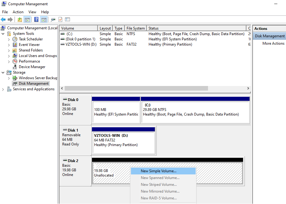
    1. Right-click the Unallocated space on the disk.
    2. Select New Simple Volume.

    New Simple Volume option

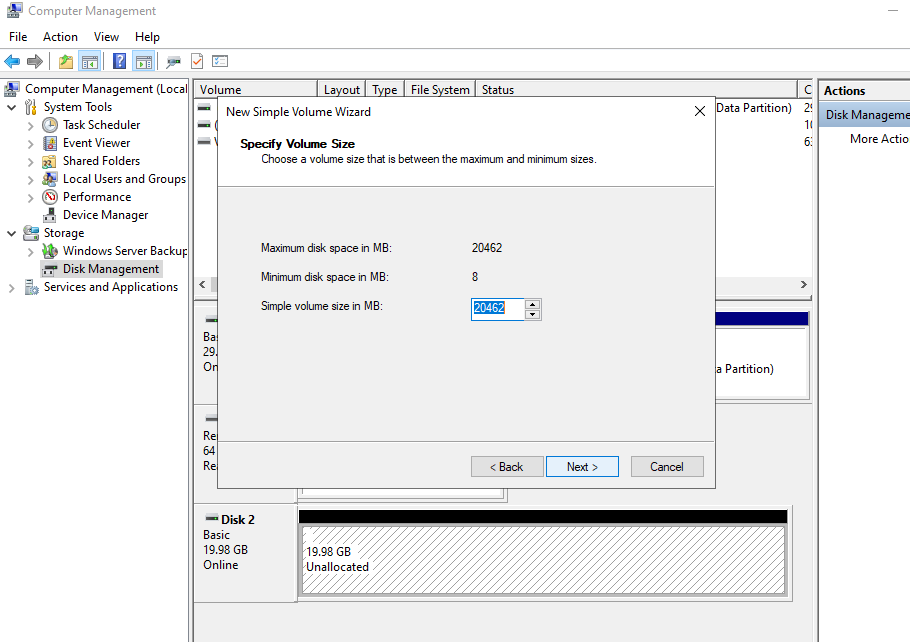
    Step 2: Specify the Volume Size

    The New Simple Volume Wizard opens.

    1. Select Next.
    2. Specify the size of the volume.
    3. Select Next.

    By default, you can use the entire available disk space for the new volume.

    Tip: If you want the entire disk to be used as a single volume, accept the default maximum volume size.

    volume size selection

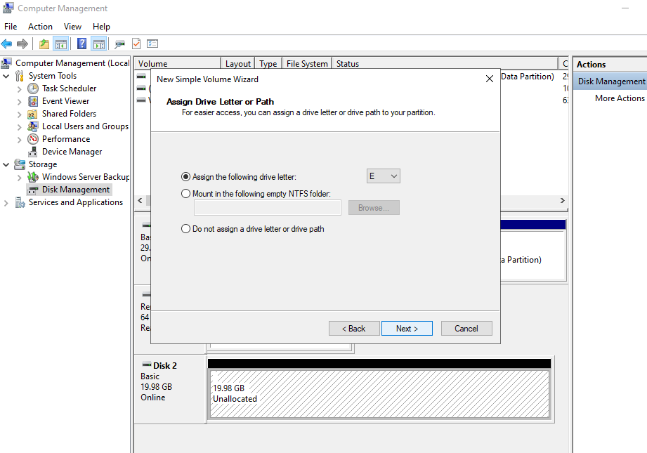
    Step 3: Assign a Drive Letter

    Specify the drive letter that you want to assign to the new volume.

    For example:

    E:

    Select Next.

    drive-letter selection

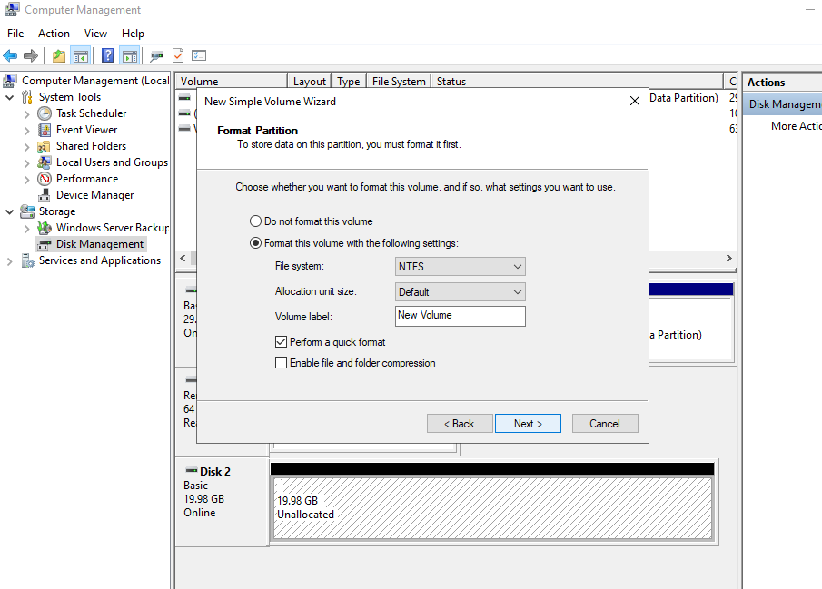
    Step 4: Format the Volume

    Specify the filesystem and volume label.

    For a typical Windows volume:

    • File system: NTFS
    • Volume label: Specify an appropriate name for the volume.

    Select Next.

    filesystem and volume label settings

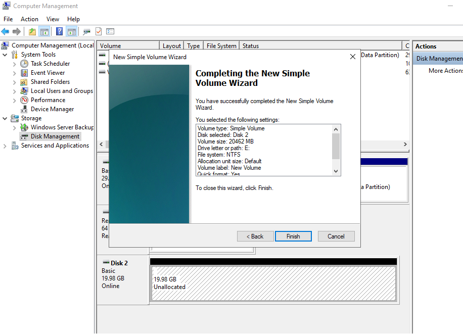
    Step 5: Complete the Wizard

    Review the selected configuration and select Finish.

    Windows will create and format the new volume.

    Wizard completion

    Verify the New Volume

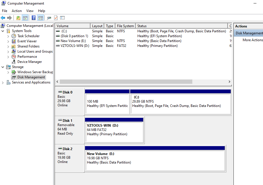
    After the wizard completes, return to Disk Management.

    The newly configured disk should be displayed as:

    Healthy (Online)

    Healthy status

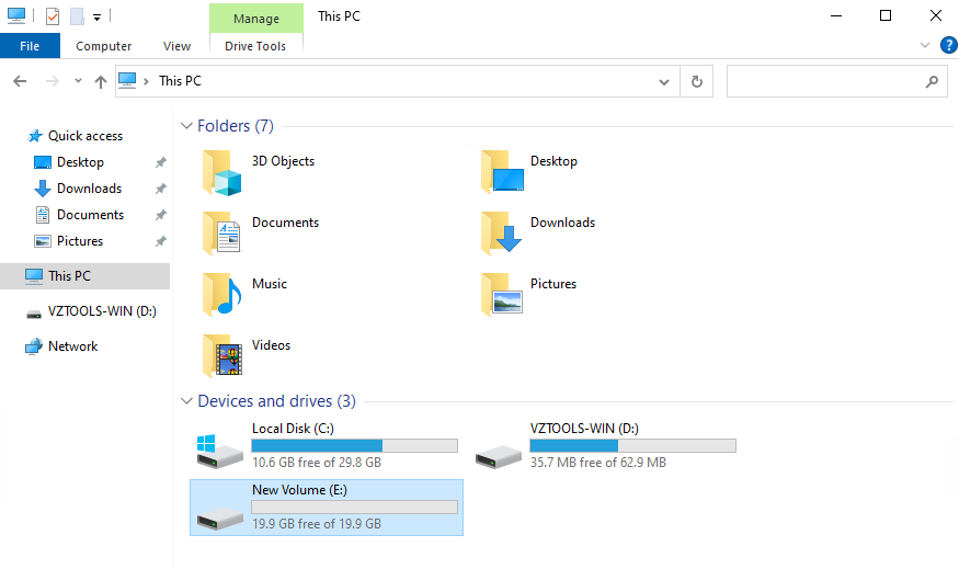
    The new volume should also be visible in File Explorer under This PC.

    For example:

    New Volume (E:)

    File Explorer

    You can now use the new volume for storing files and application data.

    Troubleshooting

    The Newly Added Disk Is Offline

    If the disk is displayed as Offline:

    1. Open Computer Management.
    2. Navigate to Storage > Disk Management.
    3. Locate the newly attached disk.
    4. Right-click the disk.
    5. Select Online.

    After the disk becomes online, continue with disk initialization.

    The Disk Shows as Not Initialized

    If the disk is displayed as Not Initialized:

    1. Right-click the disk.
    2. Select Initialize Disk.
    3. Confirm that the correct disk is selected.
    4. Select GPT.
    5. Select OK.

    The disk should then become available as Unallocated space.

    The New Volume Is Not Visible in File Explorer

    If the volume is not visible in File Explorer:

    1. Open Disk Management.
    2. Verify that the disk is Online.
    3. Confirm that the volume was successfully created.
    4. Verify that a drive letter has been assigned.
    5. Confirm that the volume is displayed as Healthy.

    If a drive letter has not been assigned, review the volume configuration in Disk Management.

    Important Notes

    • Verify the disk number before performing any disk operation.
    • An offline disk must be brought online before it can be initialized or used.
    • A disk must be initialized before creating a new volume.
    • The source procedure uses GPT as the partition style.
    • Unallocated space can be used to create a New Simple Volume.
    • The new volume can be assigned a drive letter such as E:.
    • The source procedure uses NTFS as the typical filesystem.
    • After configuration, the disk should appear as Healthy (Online) in Disk Management.
    • The new volume should be visible in File Explorer.

    Warning: Always verify the correct disk before initializing or creating volumes. Initializing or modifying the wrong disk can affect existing data.

    Related Guide

    After a newly added disk is online and initialized, you can create a new volume or use the available space to extend an existing volume.

    To know more about “How to Extend a Basic Volume on a Windows VM?”. Click Here for more details.

    Conclusion

    Managing a newly added disk on a Windows VM involves checking its status, bringing it online if required, initializing the disk, and creating a new volume. Windows Disk Management provides the required tools to complete these tasks without additional software.

    For a newly attached disk, verify that the correct disk is selected before making any changes. Once the disk is initialized and a volume is created, assign a drive letter, format the volume, and confirm that it is displayed as Healthy (Online) and available through File Explorer.

    FAQ’s

    Why is my newly added disk showing as Offline?

    A newly attached disk may sometimes be detected by Windows but remain offline because of a disk policy. You can bring it online from Computer Management > Storage > Disk Management.

    What should I do if the disk is Offline?

    Right-click the disk in Disk Management and select Online. The disk can then be initialized and configured.

    Which partition style should I select when initializing the disk?

    The source procedure recommends GPT (GUID Partition Table) as the partition style.

    Can I create a volume immediately after bringing the disk online?

    If the disk is not initialized, it must first be initialized. After initialization, the unallocated space can be used to create a new simple volume.

    How do I create a new volume on the disk?

    Right-click the Unallocated space in Disk Management and select New Simple Volume. Follow the wizard to specify the size, assign a drive letter, select the filesystem, and complete the setup.

    Which filesystem should I use for the new Windows volume?

    The source procedure uses NTFS as the typical filesystem.

    How can I verify that the new disk is ready?

    In Disk Management, verify that the disk is displayed as Healthy (Online). Then open File Explorer > This PC and confirm that the new volume and assigned drive letter are visible.

    Can I use the newly added disk to extend an existing Windows volume?

    Yes, once the disk is online and initialized, the appropriate storage configuration can be performed. For extending an existing basic volume, refer to the related How to Extend a Basic Volume on a Windows VM? guide.

  • How to Connect VMs Between Two CMP Projects Using Private IPs Through a Site-to-Site VPN?

    Introduction

    When virtual machines are deployed in different CMP projects, their private networks and virtual routers are isolated at the project level. As a result, VMs in separate projects cannot communicate directly through a shared virtual router.

    A Site-to-Site IPsec VPN can be used to securely connect the private networks of two CMP projects. Once the VPN is configured, traffic between the private networks can be routed through the VPN instead of using the public network.

    This guide explains how to create private networks, configure virtual routers, establish a Site-to-Site IPsec VPN, configure Linux VM routing, and verify private-to-private connectivity between VMs in separate CMP projects.

    Example Network Architecture

    This guide uses the following example configuration.

    Component Default 1 Default 2
    Project Default 1 Default 2
    Private Network 10.10.10.0/24 10.10.20.0/24
    Router Private IP 10.10.10.1 10.10.20.1
    VPN Public IP <DEFAULT-1-VPN-PUBLIC-IP> <DEFAULT-2-VPN-PUBLIC-IP>
    Test VM 10.10.10.93 10.10.20.178


    The expected traffic path is:

    Default 1 VM

    10.10.10.93

          |

          | Private Network

          v

    10.10.10.1

          |

          | Default 1 Router

          |

          | IPsec Site-to-Site VPN

          |

          | Default 2 Router

          v

    10.10.20.1

          |

          | Private Network

          v

    Default 2 VM

    10.10.20.178

    The final configuration allows the VMs to communicate using their private IP addresses. The public IP addresses are used only as VPN endpoints.

    Prerequisites

    Before configuring the Site-to-Site VPN, ensure that:

    • You have administrative access to both CMP projects.
    • Both projects are in the same region or in regions where VPN connectivity is supported.
    • Each project has a private network.
    • Each private network uses a different, non-overlapping CIDR.
    • Each project has a virtual router.
    • Each router has access to the public network.
    • You have administrative/root access to the VMs.
    • The required VPN ports/protocols are permitted by the network/security configuration.

    For this example:

    Default 1 Private Network:
    10.10.10.0/24

    Default 2 Private Network:
    10.10.20.0/24

    Important: Do not use the same subnet on both sides of the VPN. The private networks must use different, non-overlapping CIDRs.

    Step 1: Create a Private Network

    If a project does not have a private network, create one before configuring the router or VPN.

    Default 1

    Navigate to:

    Project → Networks → Private Networks → Create Private Network

    Example:

    Network Name: Default-1-Private
    CIDR: 10.10.10.0/24
    DHCP: Enabled

    The network gateway will be:

    10.10.10.1

    Default 2

    Switch to the second project and create another private network:

    Network Name: Default-2-Private
    CIDR: 10.10.20.0/24
    DHCP: Enabled

    The network gateway will be:

    10.10.20.1

    Important

    The private networks must not overlap.

    Correct:

    Default 1: 10.10.10.0/24
    Default 2: 10.10.20.0/24

    Incorrect:

    Default 1: 10.10.10.0/24
    Default 2: 10.10.10.0/24

    Step 2: Configure the Virtual Router

    Because CMP projects are isolated, configure a separate virtual router in each project.

    Default 1 Router

    Go to:

    Default 1 → Networks → Routers → Create Router

    Example:

    Router Name: Default-1-Router
    External Network: public
    SNAT: Enabled

    After creating the router, add the Default 1 private network as an internal interface.

    The router should have:

    External:
    Public IP: <DEFAULT-1-VPN-PUBLIC-IP>

    Internal:
    10.10.10.1

    Network:
    10.10.10.0/24

    Default 2 Router

    Switch to Default 2 and create:

    Router Name: Default-2-Router
    External Network: public
    SNAT: Enabled

    Attach the Default 2 private network.

    The router should have:

    External:
    Public IP: <DEFAULT-2-VPN-PUBLIC-IP>

    Internal:
    10.10.20.1

    Network:
    10.10.20.0/24

    At this point, the two projects should look like:

    Default 1

    10.10.10.0/24

          |

    10.10.10.1

          |

    Default-1-Router

          |

    Public IP

    <DEFAULT-1-VPN-PUBLIC-IP>


    Default 2

    10.10.20.0/24

          |

    10.10.20.1

          |

    Default-2-Router

          |

    Public IP

    <DEFAULT-2-VPN-PUBLIC-IP>

    Step 3: Configure the Site-to-Site VPN

    CMP provides an IPsec VPN configuration using IKE and IPsec policies, endpoint groups, and peer information. The local and remote subnets define the networks that should communicate through the VPN.

    3.1 Create the IKE Policy

    In Default 1, go to:

    Networks → VPNs → Create VPN

    Create a new IKE policy.

    Example:

    Policy Name: Default1-Default2-IKE
    Key Lifetime: 3600
    Authentication: SHA-256
    Encryption: AES-256
    IKE Version: IKEv2
    DH Group: Group 14

    Use matching IKE parameters on both sides.

    3.2 Create the IPsec Policy

    Create a new IPsec policy:

    Policy Name: Default1-Default2-IPsec
    Key Lifetime: 3600
    Authentication: SHA-256
    Encryption: AES-256
    DH Group: Group 14

    The IPsec settings must be compatible on both VPN peers.

    3.3 Create Default 1 Endpoint Groups

    Select:

    Router:
    Default-1-Router

    Local Endpoint

    Group Name:
    Default-1-Local

    Subnet:
    10.10.10.0/24

    Remote Endpoint

    Group Name:
    Default-2-Remote

    Subnet:
    10.10.20.0/24

    Therefore:

    Default 1

    Local Network = 10.10.10.0/24
    Remote Network = 10.10.20.0/24

    3.4 Create the Default 1 VPN

    Example:

    VPN Name:
    Default1-to-Default2

    Peer Public IP:
    <DEFAULT-2-VPN-PUBLIC-IP>

    Pre-Shared Key:
    <Strong PSK>

    The peer IP must be the public IP of the VPN router in Default 2.

    Step 4: Configure the VPN in Default 2

    Repeat the VPN configuration in Default 2.

    Use the same IKE and IPsec policy parameters.

    Router

    Default-2-Router

    Local Endpoint

    Group Name:
    Default-2-Local

    Subnet:
    10.10.20.0/24

    Remote Endpoint

    Group Name:
    Default-1-Remote

    Subnet:
    10.10.10.0/24

    Therefore:
    Default 2

    Local Network = 10.10.20.0/24
    Remote Network = 10.10.10.0/24

    VPN Configuration

    VPN Name:
    Default2-to-Default1

    Peer Public IP:
    <DEFAULT-1-VPN-PUBLIC-IP>

    Pre-Shared Key:
    <SAME PSK USED ON DEFAULT 1>

    Important: The PSK must be identical on both sides.

    The final configuration is:

    Default 1

    Local: 10.10.10.0/24
    Remote: 10.10.20.0/24
    Peer: <DEFAULT-2-VPN-PUBLIC-IP>

    Default 2

    Local: 10.10.20.0/24
    Remote: 10.10.10.0/24
    Peer: <DEFAULT-1-VPN-PUBLIC-IP>

    Step 5: Verify the VPN Status

    After creating both VPN configurations, check:

    Default 1 → Networks → VPNs

    and:

    Default 2 → Networks → VPNs

    Both VPN connections should show:

    Status: Active

    Important: The tunnel should not be considered ready until both sides are active.

    Step 6: Attach the Private Network to the VM

    The VM in each project must have an interface on its project’s private network.

    Default 1 VM

    Example:

    Private Interface:
    10.10.10.93

    Private Gateway:
    10.10.10.1

    Default 2 VM

    Example:

    Private Interface:
    10.10.20.178

    Private Gateway:
    10.10.20.1

    Verify the interfaces inside Linux:

    Bash
    ip -br addr

    Example Default 1:

    enp1s0 UP 10.10.10.93/24
    enp8s0 UP <PUBLIC-IP>

    Example Default 2:

    enp1s0 UP 10.10.20.178/24
    enp8s0 UP <PUBLIC-IP>

    Step 7: Configure the Linux VM Routing

    This step is important.

    Having an Active VPN does not automatically mean that the VM will select the VPN for traffic to the remote private subnet.

    Initially, Linux may use the public default route.
    For example:

    Bash
    ip route get 10.10.20.178

    If the result uses the public gateway/interface, the VM is not routing the traffic through the private network.
    Default 1

    Add a route for the Default 2 private network:

    Bash
    sudo ip route add 10.10.20.0/24 via 10.10.10.1 dev enp1s0

    Verify:

    Bash
    ip route get 10.10.20.178

    Expected result:

    10.10.20.178 via 10.10.10.1 dev enp1s0

    Default 2

    Add the reverse route:

    Bash
    sudo ip route add 10.10.10.0/24 via 10.10.20.1 dev enp1s0

    Verify:

    Bash
    ip route get 10.10.10.93

    Expected result:

    10.10.10.93 via 10.10.20.1 dev enp1s0

    Important

    The example interface names may differ.

    Before adding the route, identify the private interface using:

    Bash
    ip -br addr

    Warning: Do not use enp1s0 blindly if your VM uses a different interface name.

    Step 8: Verify Private-to-Private Connectivity

    Test from Default 1

    Ping the Default 2 private IP:

    Bash
    ping -c 4 10.10.20.178

    Expected:

    4 packets transmitted, 4 received, 0% packet loss

    Test SSH:

    Bash
    nc -zv 10.10.20.178 22

    Expected:

    Connection to 10.10.20.178 22 port [tcp/ssh] succeeded!

    You can also test SSH directly:

    Bash
    ssh root@10.10.20.178

    Test from Default 2

    Ping the Default 1 private IP:

    Bash
    ping -c 4 10.10.10.93

    Expected:

    4 packets transmitted, 4 received, 0% packet loss

    Step 9: Verify the Routing Path

    From Default 1:

    Bash
    ip route get 10.10.20.178

    The route should use:

    10.10.10.1 dev enp1s0

    and not the public default gateway.

    You can also use:

    Bash
    traceroute 10.10.20.178

    A working private-to-private path should show the traffic leaving through the private gateway and reaching the remote private network.

    Example:

    10.10.10.1
    10.10.10.x
    10.10.20.x

    This confirms that traffic is traversing the routed VPN path rather than using the public default route.

    Troubleshooting

    VPN Shows Inactive

    Check the following on both sides:

    • Peer public IP
    • IKE version
    • Encryption algorithm
    • Authentication algorithm
    • DH group
    • IPsec policy
    • Pre-shared key
    • Local subnet
    • Remote subnet

    Ensure that the settings are compatible on both VPN peers.

    Ping Fails but VPN Is Active

    Check the VM route:

    Bash
    ip route get <REMOTE_PRIVATE_IP>

    For example:

    Bash
    ip route get 10.10.20.178

    If the result uses the public gateway, the VM is using the public network.

    The route should instead use:

    10.10.10.1

    One Direction Works but the Reverse Direction Fails

    Check the route on the second VM.

    Default 1 must have:

    10.10.20.0/24 via 10.10.10.1

    Default 2 must have:

    10.10.10.0/24 via 10.10.20.1

    Both directions are required for normal TCP communication.

    Ping Works but SSH Does Not

    Check whether SSH is listening:

    Bash
    ss -lntp | grep :22

    Check the firewall:

    Bash
    sudo ufw status

    If CMP security groups are being used, verify that the required port is allowed from the remote private subnet.

    For example:

    Source: 10.10.10.0/24
    Destination Port: 22
    Protocol: TCP

    The Route Disappears After Reboot

    Routes added with:

    Bash
    ip route add

    are runtime configuration and may not survive a reboot or network restart.

    For production use, configure the route persistently using the networking method appropriate for the Linux distribution, such as Netplan on Ubuntu.

    Verification Checklist

    After completing the configuration, verify:

    • Default 1 private network created.
    • Default 2 private network created.
    • CIDRs are non-overlapping.
    • Router created in Default 1.
    • Router created in Default 2.
    • Private networks attached to routers.
    • IKE policy configured.
    • IPsec policy configured.
    • VPN configured on Default 1.
    • VPN configured on Default 2.
    • VPN status is Active on both sides.
    • Default 1 VM is attached to 10.10.10.0/24.
    • Default 2 VM is attached to 10.10.20.0/24.
    • Route configured on Default 1 VM.
    • Route configured on Default 2 VM.
    • Ping succeeds between private IPs.
    • Application port connectivity succeeds.

    Summary

    To connect VMs located in different CMP projects using private networking:

    1. Create a private network in each project.
    2. Ensure the private CIDRs do not overlap.
    3. Create a virtual router in each project.
    4. Attach each private network to its corresponding router.
    5. Configure compatible IKE and IPsec policies.
    6. Configure the Site-to-Site VPN on both routers.
    7. Verify that both VPN connections show Active.
    8. Attach the private networks to the VMs.
    9. Configure Linux routes for the remote private subnet.
    10. Verify private-to-private connectivity.

    The final configuration is:

    Default 1                                    Default 2


    10.10.10.0/24                               10.10.20.0/24

          |                                           |

        VM-A                                        VM-B

    10.10.10.93                               10.10.20.178

          |                                           |

      10.10.10.1                                 10.10.20.1

          |                                           |

    Default-1-Router                            Default-2-Router

          |                                           |

          +————- IPsec VPN ——————+

    This provides private-to-private communication between VMs in separate CMP projects, while the public IP addresses are used only as VPN endpoints.

    Conclusion

    A Site-to-Site IPsec VPN provides a secure way to connect private networks belonging to separate CMP projects when the projects cannot share a common virtual router.

    The key components are the private networks, project-specific routers, IPsec VPN configuration, and correct VM routing.

    After configuration, always verify that the VM sends traffic to the remote private subnet through its private gateway, rather than through the public default route.

    FAQ’s

    Can I connect two projects using a single router?

    No. In this configuration, each CMP project uses its own router, and the two routers are connected through the Site-to-Site VPN.

    Do both projects need a private network?

    Yes. Each project needs a private subnet for private VM-to-VM communication.

    Can both private networks use the same CIDR?

    No. The local and remote networks must use different, non-overlapping CIDRs.

    Does an Active VPN automatically change the VM’s routing?

    No. An Active VPN does not automatically mean that the VM will use the VPN for remote private-subnet traffic. The VM must have a route directing the remote private subnet to its local private gateway.

    Should VM-to-VM traffic use the public IP?

    No. Application traffic should use the private IP addresses. The public IP addresses are used only as VPN peer endpoints.

    How can I verify that the VM is using the VPN?

    Run:

    Bash
    ip route get <REMOTE_PRIVATE_IP>

    The route should point to the VM’s private gateway/interface, not the public gateway.

    How can I verify application connectivity?

    Use the appropriate test, for example:

    Bash
    ping <REMOTE_PRIVATE_IP>
    nc -zv <REMOTE_PRIVATE_IP> 22
    ssh user@<REMOTE_PRIVATE_IP>

    Are the Linux routes persistent?

    Routes added with ip route add are normally runtime routes. For production deployments, configure them persistently through the operating system’s network configuration.

  • Migrate Wasabi to CMP S3 Storage for WindowsOS Using Rclone

    Introduction

    This guide walks you through migrating data from Wasabi cloud storage to CMP S3-compatible storage using rclone, a powerful command-line tool for managing files across cloud storage providers. Whether you are consolidating storage, switching providers, or setting up a backup strategy, rclone makes the process straightforward and reliable.

    Migrating between S3-compatible storage platforms requires correctly configuring source and destination remotes, ensuring credentials and endpoints are accurate, and verifying the transfer. This article covers every step – from installing rclone on Windows to confirming your data has arrived safely in CMP.

    Prerequisites

    Before you begin, ensure you have the following:

    Windows 10 or later with administrative access
    Windows Package Manager (winget) installed (included by default in Windows 10 1709+ and Windows 11)
    Wasabi account credentials:
    o Access Key ID
    o Secret Access Key
    o Your Wasabi region and service URL (refer to Wasabi’s Service URLs documentation)
    CMP account credentials:
    o Access Key ID (User ID)
    o Secret Access Key
    o Your CMP region and S3 endpoint (available from the CMP portal under Object Storage → Access)
    • An existing bucket in CMP where the migrated data will be stored
    Note: Keep your Access Key IDs and Secret Access Keys secure. Never share them in public repositories or unencrypted communications.

    Installing Rclone on Windows

    The fastest way to install rclone on Windows is through the Windows Package Manager (winget).

    1. Open PowerShell as Administrator (right-click → Run as administrator).
    2. Run the following command:

    PowerShell
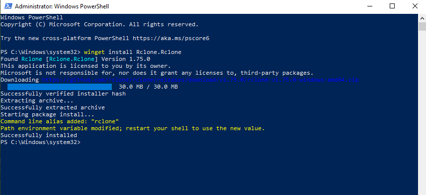
    winget install Rclone.Rclone

    3. Wait for the download and installation to complete. You should see output confirming the installation was successful.

    Rclone installed successfully

    Figure 1: Rclone installed successfully via winget. Note the message to restart your shell to use the new PATH.
    4. Close and reopen PowerShell to ensure the updated PATH environment variable is loaded.
    5. Verify the installation by running:
    rclone version

    Configuring the Wasabi Source Remote

    The first step is to configure rclone with your Wasabi storage as the source remote. This tells rclone how to connect to your Wasabi account and access your buckets.

    Step 1 — Launch Rclone Configuration

    1. Open PowerShell (Administrator is not required for configuration).
    2. Run:

    PowerShell
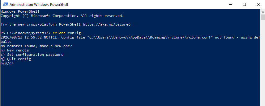
    rclone config

    3. If this is your first time running rclone, you will see a message that no remotes are found. Select n to create a new remote.

    rclone config

    Figure 2: Rclone configuration menu — no remotes found. Select n to create a new remote.

    Step 2 — Name the Remote and Select Storage Type

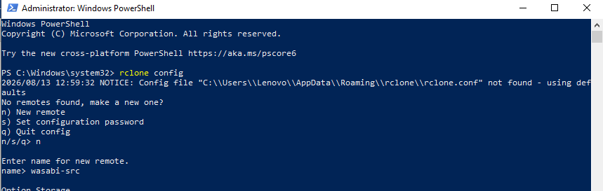
    1. When prompted for a name, enter wasabi-src (or any descriptive name for your Wasabi source).
    2. For Option Storage (type of storage to configure), type s3 and press Enter.

    storage type

    Figure 3: Enter the remote name wasabi-src and select s3 as the storage type.

    3. For Option provider (Choose your S3 provider), you will see a numbered list of S3-compatible providers. Type 53 to select “Any other S3 compatible provider” (Other) and press Enter.

    Choose your S3 provider

    Figure 4: The S3 provider selection prompt appears after choosing s3 storage.

    Step 3 — Enter Authentication Credentials

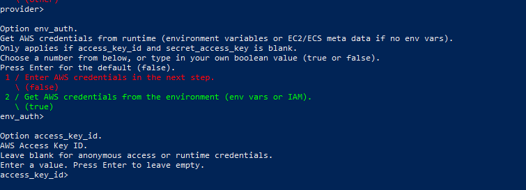
    1. For Option env_auth, press Enter to accept the default (false). This tells rclone you will enter credentials manually in the next step.
    2. For Option access_key_id, enter your Wasabi Access Key ID and press Enter.
    3. For Option secret_access_key, enter your Wasabi Secret Access Key and press Enter.

    Enter Authentication Credentials

    Figure 5: Select false for env_auth, then enter your Wasabi Access Key ID and Secret Access Key when prompted.

    Warning: The credentials shown in the screenshots are from a test environment. Always use your own Wasabi Access Key ID and Secret Access Key. Never share these credentials publicly.

    Step 4 — Set Region and Endpoint

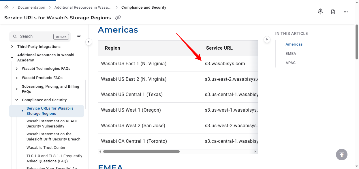
    Before entering the region and endpoint, you need to know which Wasabi region your bucket is hosted in. Refer to the Wasabi Service URLs documentation to find the correct service URL for your region.

    Set Region and Endpoint

    Figure 6: Wasabi’s Service URLs page — find the service URL that corresponds to your storage region.

    The table below lists commonly used Wasabi regions and their service URLs:
    Region Service URL
    Wasabi US East 1 (N. Virginia) s3.wasabisys.com
    Wasabi US East 2 (N. Virginia) s3.us-east-2.wasabisys.com
    Wasabi US Central 1 (Texas) s3.us-central-1.wasabisys.com
    Wasabi US West 1 (Oregon) s3.us-west-1.wasabisys.com
    Wasabi CA Central 1 (Toronto) s3.ca-central-1.wasabisys.com
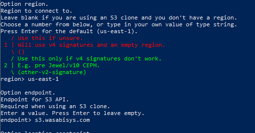
    1. For Option region, enter your Wasabi region (e.g., us-east-1).
    2. For Option endpoint, enter the corresponding Wasabi service URL (e.g., s3.wasabisys.com).

    Enter the region

    Figure 7: Enter the region (e.g., us-east-1) and endpoint (e.g., s3.wasabisys.com) for your Wasabi storage.

    Step 5 — Skip Advanced Options and Confirm

    1. For the remaining options (location_constraint, acl, server_side_encryption, sse_kms_key_id, etc.), press Enter to accept the defaults unless you have specific requirements.
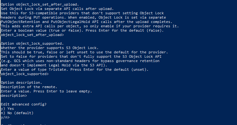
    2. When you reach object_lock_set_after_upload, object_lock_supported, and description, press Enter to skip each one.
    3. When prompted “Edit advanced config?”, select n (No).

    Enter to skip advanced options

    Figure 8: Press Enter to skip advanced options like object_lock and description. Select n for “Edit advanced config?”.

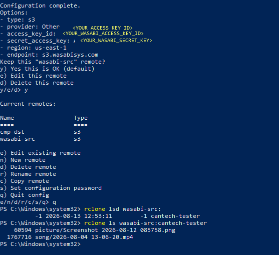
    4. Rclone will display a summary of your configuration. Review it carefully and select y (Yes this is OK) to confirm.

    Step 6 — Verify the Wasabi Source Remote

    After confirming the configuration, verify that rclone can connect to your Wasabi storage:
    1. Quit the configuration menu by pressing q.
    2. List your Wasabi buckets:

    PowerShell
    rclone lsd wasabi-src
    :

    3. List the contents of a specific bucket:

    PowerShell
    rclone ls wasabi-src:<bucket-name
    >

    verify rclone connection

    Figure 9: The Wasabi source remote configuration is confirmed. The rclone lsd command lists the bucket, and rclone ls shows the files inside it.

    Tip: If the rclone lsd command returns an error, double-check your Access Key ID, Secret Access Key, region, and endpoint values. Re-run rclone config to edit the remote if needed.

    Configuring the CMP Destination Remote

    Next, configure rclone with your CMP S3-compatible storage as the destination remote.

    Step 1 — Create a New Remote

    1. Run rclone config again (or if you are still in the configuration menu, select n for a new remote).
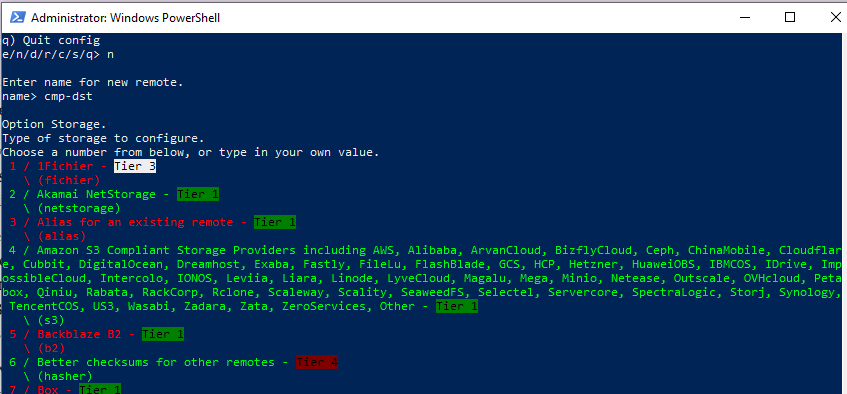
    2. Enter cmp-dst as the name for your CMP destination remote.
    3. For Option Storage, select s3.

    Create a New Remote

    Figure 10: Create a new remote named cmp-dst and select s3 (option 4 — Amazon S3 Compliant Storage Providers).

    Step 2 — Select the Provider

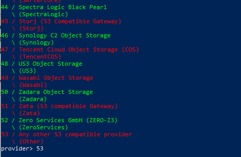
    1. For Option provider, scroll through the list or type 53 to select “Any other S3 compatible provider” (Other).

    Select the Provider again

    Figure 11: Select provider 53 — “Any other S3 compatible provider” — since CMP uses an S3-compatible API.

    Step 3 — Enter Authentication Credentials

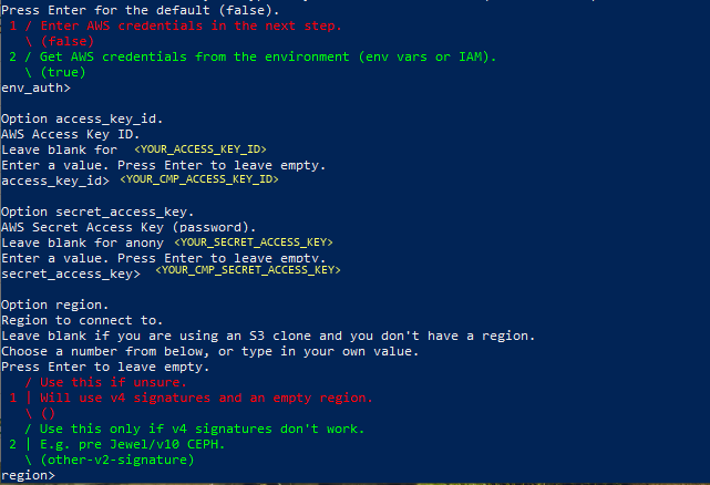
    1. For Option env_auth, press Enter to accept the default (false).
    2. For Option access_key_id, enter your CMP Access Key ID (User ID).
    3. For Option secret_access_key, enter your CMP Secret Access Key.
    You can find your CMP credentials in the CMP portal under Object Storage → Access.

    Enter Authentication Credentials again

    Figure 12: Enter your CMP Access Key ID and Secret Access Key when prompted.

    Warning: The credentials shown in the screenshots are from a test environment. Always use your own CMP credentials.

    Step 4 — Find Your CMP Region and Endpoint

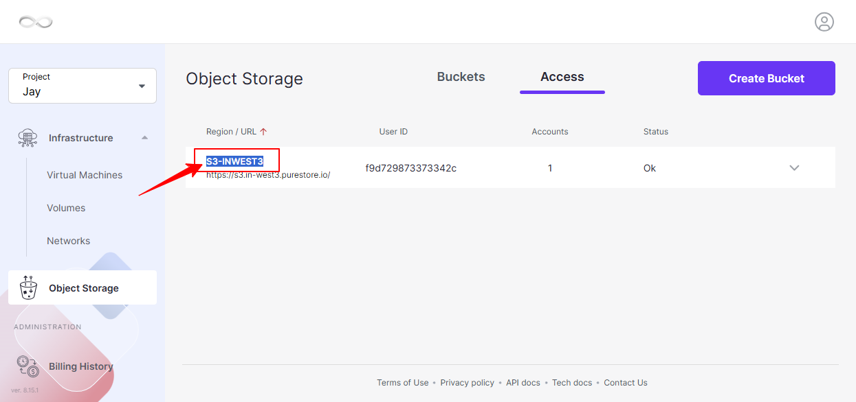
    Log in to your CMP portal and navigate to Object Storage → Access to find your region and endpoint URL.

    Find Your CMP Region and Endpoint

    Figure 13: The CMP portal’s Object Storage Access tab displays your region (e.g., S3-INWEST3) and endpoint URL (e.g., s3.in-west3.purestore.io).

    Note the following from the CMP portal:
    Field Value (Example)
    Region S3-INWEST3
    Endpoint URL https://s3.in-west3.purestore.io/
    User ID Your CMP User ID

    Step 5 — Set Region and Endpoint

    1. For Option region, enter your CMP region (e.g., S3-INWEST3).
    2. For Option endpoint, enter your CMP S3 endpoint without the protocol prefix (e.g., s3.in-west3.purestore.io).

    Set Region and Endpoint again

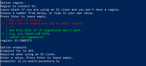
    Figure 14: Enter the CMP region (e.g., S3-INWEST3) and endpoint (e.g., s3.in-west3.purestore.io).

    3. For the remaining options, press Enter to accept defaults.
    4. When prompted “Edit advanced config?”, select n (No).

    Step 6 — Confirm and Verify the CMP Destination Remote

    1. Review the configuration summary and select y to confirm.
    2. Quit the configuration menu by pressing q.
    3. Verify the connection by listing your CMP buckets:

    PowerShell
    rclone lsd cmp-dst:

    Confirm and Verify the Destination Remote

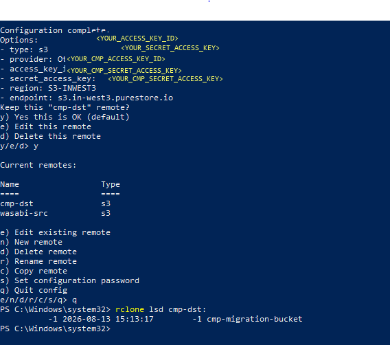
    Figure 15: The CMP destination remote is confirmed. Both wasabi-src and cmp-dst remotes are listed. The rclone lsd command shows the destination bucket.

    Running the Migration

    With both remotes configured, you can now migrate data from Wasabi to CMP.

    Copy an Entire Bucket

    To copy all data from a Wasabi bucket to a CMP bucket, run:
    rclone copy wasabi-src:<wasabi-bucket-name> cmp-dst:<cmp-bucket-name> –progress

    Example:
    rclone copy wasabi-src:cantech-tester cmp-dst:cmp-migration-bucket –progress

    Copy a Specific Folder

    To copy only a specific folder within a bucket:
    rclone copy wasabi-src:<wasabi-bucket-name>/<folder-name> cmp-dst:<cmp-bucket-name>/<folder-name> –progress

    Sync (Mirror) a Bucket

    If you want the destination to be an exact mirror of the source (deleting files in the destination that are not in the source), use rclone sync instead:
    rclone sync wasabi-src:<wasabi-bucket-name> cmp-dst:<cmp-bucket-name> –progress

    Warning: rclone sync will delete files in the destination that do not exist in the source. Use rclone copy if you want to preserve existing files in the destination bucket.

    The following table summarizes the key rclone commands for migration:

    CommandBehaviorUse When
    rclone copyCopies files from source to destination; does not delete destination filesYou want to add data without affecting existing files
    rclone syncMakes destination identical to source; deletes extra destination filesYou want an exact mirror of the source
    rclone moveMoves files from source to destination; deletes source files after transferYou want to transfer and remove from the source

    Useful Flags

    FlagDescription
    –progressDisplays real-time transfer progress
    –dry-runSimulates the operation without transferring any files
    –transfers NSets the number of parallel file transfers (default: 4)
    –checkers NSets the number of parallel checkers (default: 8)
    –log-file Writes logs to a file for later review
    –verboseIncreases output verbosity for debugging

    Tip: Always run with –dry-run first to preview what will be transferred before executing the actual migration.

    Verifying the Migration

    After the migration completes, verify that your data has been successfully transferred.

    Verify via Command Line

    1. List the contents of the destination bucket:
    rclone ls cmp-dst:<cmp-bucket-name>
    2. Compare the source and destination to ensure they match:
    rclone check wasabi-src:<wasabi-bucket-name> cmp-dst:<cmp-bucket-name>

    Verify via CMP Portal

    1. Log in to the CMP portal.
    2. Navigate to Object Storage and open your destination bucket.
    3. Confirm that all expected folders and files are present.

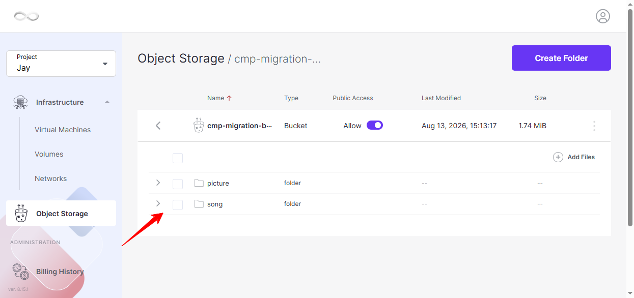
    Verify via CMP Portal

    Figure 16: The CMP portal confirms the migration — the picture and song folders are now visible in the cmp-migration-bucket.

    Conclusion

    Migrating data from Wasabi to CMP S3 storage using rclone is a reliable and efficient process. By configuring two S3-compatible remotes — one for your Wasabi source and one for your CMP destination — you can seamlessly transfer buckets, folders, or individual files between providers.
    The most important takeaway is to verify your credentials, region, and endpoint settings for both the source and destination before starting the migration. Incorrect values will cause connection failures that can be easily avoided by referencing the Wasabi service URLs documentation and the CMP portal’s Object Storage Access tab.

    For ongoing synchronization needs, consider scheduling rclone sync as a recurring task to keep your CMP storage in sync with Wasabi.

    Frequently Asked Questions

    Q1: What is rclone and why is it recommended for S3 migrations?

    Rclone is an open-source command-line tool designed for managing and transferring files across cloud storage providers. It supports over 70 storage backends, including all S3-compatible services, making it ideal for migrations between providers like Wasabi and CMP.

    Q2: Where do I find my Wasabi Access Key ID and Secret Access Key?

    Log in to your Wasabi console and navigate to Access Keys under your account settings. You can create a new access key pair if you do not have one.

    Q3: Where do I find my CMP Access Key ID, region, and endpoint?

    In the CMP portal, navigate to Object Storage → Access. Your User ID serves as the Access Key ID, and the region and endpoint URL are displayed on the same page.

    Q4: What is the difference between rclone copy and rclone sync?

    rclone copy transfers files from source to destination without modifying or deleting existing files in the destination. rclone sync makes the destination an exact mirror of the source, which means it will delete files in the destination that do not exist in the source.

    Q5: Can I migrate only specific folders or files instead of an entire bucket?

    Yes. Specify the folder path after the bucket name in the rclone command. For example: rclone copy wasabi-src:my-bucket/my-folder cmp-dst:my-bucket/my-folder.

    Q6: Why does rclone ask me to select provider “53 / Any other S3 compatible provider”?

    Both Wasabi and CMP use S3-compatible APIs. Selecting provider 53 (Other) allows you to manually enter the region and endpoint for any S3-compatible service, giving you full control over the connection settings.

    Q7: The rclone lsd command returns an error. How do I fix it?

    Common causes include incorrect Access Key ID or Secret Access Key, wrong region or endpoint values, or network connectivity issues. Run rclone config and select e (Edit existing remote) to review and correct your settings.

    Q8: Can I resume a failed or interrupted migration?

    Yes. Rclone automatically skips files that already exist in the destination (if they have the same size and modification time). Simply re-run the same rclone copy command to resume from where it left off.

  • How to Manage Volume Snapshots in Kubernetes?

    Introduction

    Kubernetes volume snapshots allow you to capture the contents of a Persistent Volume at a specific point in time. Snapshots can be useful for recovering volume data after accidental deletion, corruption, or data loss.

    In CMP Kubernetes environments, volume snapshots are implemented using Kubernetes Custom Resource Definitions (CRDs) and the snapshot-controller. These components must be installed and configured before volume snapshots can be created.

    This guide explains how to install the required snapshot components, create a VolumeSnapshotClass, create a volume snapshot from an existing PersistentVolumeClaim (PVC), verify the snapshot, and delete it when it is no longer required.

    Important: Creating a volume snapshot does not modify or move the data stored on the source volume.

    Prerequisites

    Before managing volume snapshots, ensure the following requirements are met.

    Persistent Volume Claim

    An existing PersistentVolumeClaim (PVC) must be available in the Kubernetes cluster.

    The snapshot is created from the volume associated with the PVC.

    CSI Snapshotter Version

    The CSI snapshotter version used with this procedure must not be higher than:

    release-5.0

    Warning: The source documentation states that using a CSI snapshotter version higher than release-5.0 is not supported and may cause the snapshot CRDs or snapshot-controller to behave unexpectedly.

    Required Components

    • VolumeSnapshotClass CRD
    • VolumeSnapshotContent CRD
    • VolumeSnapshot CRD
    • Snapshot-controller RBAC resources
      • ClusterRole
      • ServiceAccount
      • ClusterRoleBinding
      • Role
      • RoleBinding
    • Snapshot-controller deployment

    Install the Volume Snapshot Components

    The source procedure uses manifests from the upstream Kubernetes CSI external-snapshotter repository and follows an Infrastructure as Code (IaC) approach.

    Phase A: Clone the External Snapshotter Repository

    Clone the repository and check out the supported release:

    git clone https://github.com/kubernetes-csi/external-snapshotter/
    cd ./external-snapshotter
    git checkout release-5.0

    Important: Use the release-5.0 version specified by the source documentation for this procedure.

    Phase B: Apply the Snapshot CRDs

    Apply the required VolumeSnapshotClass, VolumeSnapshotContent, and VolumeSnapshot CRDs:

    kubectl apply -f client/config/crd/snapshot.storage.k8s.io_volumesnapshotclasses.yaml kubectl apply -f client/config/crd/snapshot.storage.k8s.io_volumesnapshotcontents.yaml
    kubectl apply -f client/config/crd/snapshot.storage.k8s.io_volumesnapshots.yaml

    These commands install the Kubernetes resources required for managing volume snapshots.

    Phase C: Deploy the Snapshot Controller

    Apply the required RBAC resources and snapshot-controller deployment in the kube-system namespace:

    kubectl apply -f deploy/kubernetes/snapshot-controller/rbac-snapshot-controller.yaml -n kube-system
    kubectl apply -f deploy/kubernetes/snapshot-controller/setup-snapshot-controller.yaml -n kube-system

    These manifests create the required:

    • Snapshot CRDs
    • ClusterRole
    • ServiceAccount
    • ClusterRoleBinding
    • Role
    • RoleBinding
    • snapshot-controller deployment

    Create a Volume Snapshot

    After the required snapshot components have been installed, you can create a volume snapshot from an existing PVC.

    Phase A: Define a VolumeSnapshotClass

    Create a file named:

    snapshot-class.yaml

    Add the following configuration:

    vi snapshot-class.yaml
    apiVersion: snapshot.storage.k8s.io/v1
    kind: VolumeSnapshotClass
    metadata:
    name: mysnapclass
    driver: cinder.csi.openstack.org
    deletionPolicy: Delete
    parameters:
    force-create: “true”

    This configuration creates a VolumeSnapshotClass named mysnapclass using the Cinder CSI driver.

    The configuration uses:

    deletionPolicy: Delete

    With the Delete policy, deleting the associated VolumeSnapshot also removes the underlying storage snapshot and the associated VolumeSnapshotContent object.

    If you want to preserve the underlying snapshot after deleting the VolumeSnapshot object, use:

    deletionPolicy: Retain

    With Retain, the underlying snapshot and VolumeSnapshotContent are retained.

    Apply the VolumeSnapshotClass

    Run:

    Bash
    kubectl apply -f snapshot-class.yaml

    Expected output:

    volumesnapshotclass.snapshot.storage.k8s.io/mysnapclass created

    Define a VolumeSnapshot

    Create a file named:

    snapshot.yaml

    Add the following configuration:

    vi snapshot.yaml
    apiVersion: snapshot.storage.k8s.io/v1
    kind: VolumeSnapshot
    metadata:
    name: mysnapshot
    spec:
    volumeSnapshotClassName: mysnapclass
    source:
    persistentVolumeClaimName: mypvc

    This configuration:

    • Creates a snapshot named mysnapshot.
    • Uses the mysnapclass VolumeSnapshotClass.
    • Creates the snapshot from the PVC named mypvc.

    Note: Replace mypvc with the name of the PVC that you want to snapshot.

    Create the Volume Snapshot

    Run:

    Bash
    kubectl create -f snapshot.yaml

    Expected output:

    volumesnapshot.snapshot.storage.k8s.io/mysnapshot created

    The newly created snapshot will appear in the CMP self-service panel under:

    Compute → Volumes → [Volume] → Snapshots

    Verify the Volume Snapshot

    You can verify the available volume snapshots using:

    Bash
    kubectl get vs

    This command displays the VolumeSnapshot resources available in the Kubernetes environment.

    Delete a Volume Snapshot

    When a volume snapshot is no longer required, it can be deleted using the manifest that was used to create it.

    Run:

    Bash
    kubectl delete -f snapshot.yaml

    Expected output:

    volumesnapshot.snapshot.storage.k8s.io “mysnapshot” deleted

    Important: Whether the underlying storage snapshot is also deleted depends on the deletionPolicy configured in the associated VolumeSnapshotClass.

    Delete Policy: Delete

    If the VolumeSnapshotClass uses:

    deletionPolicy: Delete

    the underlying storage snapshot and VolumeSnapshotContent are removed when the VolumeSnapshot is deleted.

    Delete Policy: Retain

    If the VolumeSnapshotClass uses:

    deletionPolicy: Retain

    the underlying storage snapshot and VolumeSnapshotContent remain after the VolumeSnapshot is deleted.

    Choose the policy according to the required retention and recovery behavior.

    Safety and Recovery

    Data Integrity

    Creating a volume snapshot does not alter, move, or delete the data stored on the source volume.

    The snapshot captures the volume state at the time it is created and can be used for recovery purposes later.

    Version Compatibility

    The source procedure supports a CSI snapshotter version no higher than:

    release-5.0

    Using a higher version is not supported by this documentation and may cause unexpected behavior with the snapshot CRDs or snapshot-controller.

    Snapshot Best Practices

    For critical workloads:

    • Take snapshots regularly.
    • Consider creating a snapshot before major workload changes or upgrades.
    • Use the Retain deletion policy for critical volumes when you need the underlying snapshot to survive accidental deletion of the VolumeSnapshot object.

    Warning: A snapshot should be treated as part of your recovery strategy. Ensure that the selected deletion policy matches your intended snapshot-retention requirements.

    Troubleshooting and Important Considerations

    Snapshot Creation Fails

    If a VolumeSnapshot cannot be created, verify:

    1. The required snapshot CRDs are installed.
    2. The snapshot-controller is deployed.
    3. The required RBAC resources are available.
    4. A valid VolumeSnapshotClass exists.
    5. The referenced PVC exists.
    6. The CSI snapshotter version is supported by this procedure.

    The VolumeSnapshot Is Not Listed

    If the snapshot does not appear when running:

    Bash
    kubectl get vs

    verify that the VolumeSnapshot resource was created successfully and that the Kubernetes snapshot components have been installed.

    Snapshot Deletion Behavior Is Unexpected

    Check the deletionPolicy configured in the associated VolumeSnapshotClass.

    For example:

    deletionPolicy: Delete

    and:

    deletionPolicy: Retain

    have different effects on the underlying storage snapshot.

    Summary

    Kubernetes volume snapshots provide a way to capture the state of a Persistent Volume at a specific point in time.

    The CMP procedure requires:

    1. An existing PersistentVolumeClaim.
    2. Supported CSI snapshotter components.
    3. The required Kubernetes snapshot CRDs.
    4. The snapshot-controller and its RBAC resources.
    5. A VolumeSnapshotClass.
    6. A VolumeSnapshot referencing the required PVC.

    Snapshots can be verified using:

    Bash
    kubectl get vs

    When a snapshot is no longer required, it can be deleted using:

    Bash
    kubectl delete -f snapshot.yaml

    The effect of deleting the snapshot depends on whether the associated VolumeSnapshotClass uses the Delete or Retain deletion policy.

    Conclusion

    Managing volume snapshots in Kubernetes provides an effective way to capture PVC data at a specific point in time for recovery purposes. Before creating snapshots, ensure that the required CRDs, snapshot-controller, RBAC resources, and supported CSI snapshotter components are installed.

    When creating snapshots, carefully select the VolumeSnapshotClass and its deletion policy. For critical volumes where the underlying snapshot should survive deletion of the Kubernetes snapshot object, the source documentation recommends using the Retain policy.

    Following these steps allows Kubernetes volume snapshots to be created, verified, and deleted in a controlled manner within CMP.

    FAQ’s

    What is a Kubernetes volume snapshot?

    A Kubernetes volume snapshot captures the contents of a Persistent Volume at a specific point in time. It can be used for recovery purposes if volume data is accidentally deleted, corrupted, or lost.

    Does creating a snapshot modify the source volume?

    No. Creating a volume snapshot does not modify or move the data on the source volume.

    What is required before creating a VolumeSnapshot?

    An existing PVC, the required volume snapshot CRDs, snapshot-controller, RBAC resources, a VolumeSnapshotClass, and a supported CSI snapshotter are required.

    Which CSI snapshotter version is supported by this procedure?

    The source documentation specifies that the CSI snapshotter version must not be higher than release-5.0.

    How do I create a Kubernetes volume snapshot?

    Create a VolumeSnapshot manifest referencing the required PVC and VolumeSnapshotClass, then run:

    Bash
    kubectl create -f snapshot.yaml

    How can I verify existing volume snapshots?

    Run:

    Bash
    kubectl get vs

    This lists the VolumeSnapshot resources available in the cluster.

    What is the difference between Delete and Retain?

    With Delete, deleting the VolumeSnapshot also removes the underlying storage snapshot and VolumeSnapshotContent. With Retain, the underlying snapshot and VolumeSnapshotContent are preserved.

    How do I delete a volume snapshot?

    Run:

    Bash
    kubectl delete -f snapshot.yaml

    The effect on the underlying storage snapshot depends on the configured deletionPolicy.

  • How to Extend a Basic Volume on a Windows VM?

    Introduction

    You can increase the size of an existing basic volume on a Windows virtual machine by using available unallocated space on the same disk. Windows provides the Disk Management utility to view available disk space and extend an existing volume without creating a new volume.

    This guide explains how to identify unallocated space, verify the required conditions, and extend a basic volume using the Extend Volume Wizard. It also explains how to verify the updated capacity after the operation is complete.

    Prerequisites

    Before extending a basic volume, ensure the following requirements are met:

    • Unallocated space must be directly next to the volume that you want to extend.
    • There must be no other volume between the target volume and the unallocated space.
    • The unallocated space must be on the same disk as the volume you want to extend.
    • A volume cannot be extended across different disks using this procedure.

    Important: If the unallocated space is not directly adjacent to the volume, the Extend Volume option may not be available in Disk Management.

    View Unallocated Space

    You can use Windows Disk Management to view the available disk space and identify unallocated space.

    Step 1: Open Computer Management

    Open the Computer Management console by searching for Computer Management from the Windows taskbar.

    Step 2: Open Disk Management

    Navigate to:

    Storage > Disk Management

    The Disk Management window displays the available disks and their partitions.

    Step 3: Identify Unallocated Space

    Review the disk layout and identify the available unallocated space.

    In Disk Management, unallocated space is displayed as a black bar with the label Unallocated.

    If multiple disks are attached to the VM, select the appropriate disk and review its partitions and available unallocated space.

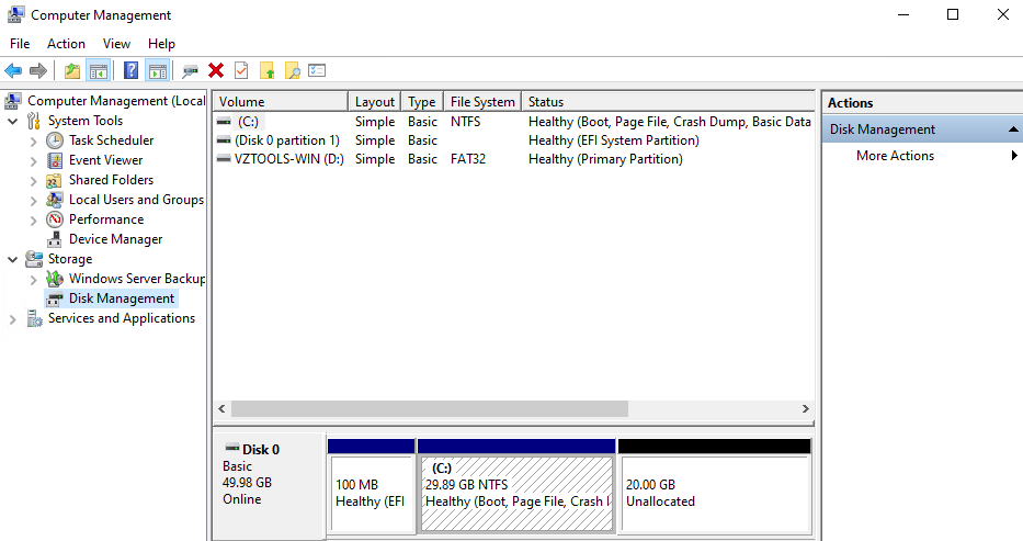
    Windows Disk Management

    Note: Confirm that the unallocated space is on the same disk and directly adjacent to the volume that you want to extend.

    Extend a Basic Volume

    Once the required unallocated space has been identified, follow the steps below to extend the volume.

    Step 1: Open the Extend Volume Wizard

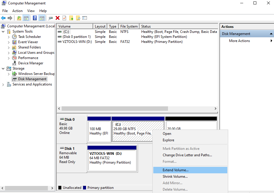
    In Disk Management, right-click the volume that you want to extend and select Extend Volume.

    The Extend Volume Wizard will open.

    Extend Volume

    Step 2: Continue with the Wizard

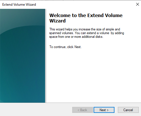
    In the Extend Volume Wizard, select Next.

    Extend Volume Wizard

    Step 3: Select the Amount of Disk Space

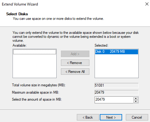
    Under Select Disks, specify how much of the available disk space you want to use to extend the volume.

    By default, Windows selects the Maximum available space.

    If you want to keep some of the unallocated space available for creating another volume, enter a smaller amount.

    Wizard showing the available disk space

    Tip: If you want to use all available unallocated space for the existing volume, keep the default maximum value.

    Step 4: Complete the Extension

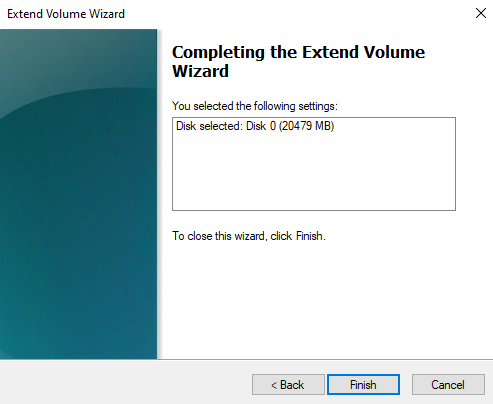
    Select Next and then select Finish to complete the operation.

    Windows will extend the selected volume using the specified amount of unallocated space.

    Wizard confirmation screen

    Step 5: Verify the Expanded Volume

    After the operation is completed, return to Disk Management.

    The volume should now appear with its increased capacity.

    Windows Disk Management

    You can also open File Explorer and verify that the disk shows the updated capacity.

    File Explorer

    Secondary Volume Attached to a Windows VM

    If a secondary volume has been attached to a Windows VM, the new disk may not immediately appear in File Explorer.

    Windows may display a newly attached disk as Offline or Unallocated.

    To make the new disk usable, it must first be brought online and initialized using the Disk Management utility.

    To know more about “How to Manage Newly Added Disks on a Windows VM?”. Click Here for more details.

    Troubleshooting

    Extend Volume Option Is Not Available

    If Extend Volume is unavailable when you right-click the volume, verify the following:

    • Unallocated space is available.
    • The unallocated space is directly next to the volume.
    • There is no other partition or volume between the target volume and the unallocated space.
    • The unallocated space is on the same disk as the target volume.

    The Additional Space Is on Another Disk

    The basic volume cannot be extended across different disks using this procedure.

    Verify the disk layout in Disk Management and ensure that the required unallocated

    space exists on the same disk as the volume you want to extend.

    The Updated Capacity Is Not Visible

    After completing the extension:

    1. Open Disk Management and verify the volume size.
    2. Open File Explorer.
    3. Check the available capacity of the corresponding drive.

    If the volume still shows the previous capacity, refresh Disk Management and verify that the extension operation completed successfully.

    Conclusion

    Extending a basic volume on a Windows VM in CMP allows you to increase an existing volume by using available unallocated space on the same disk.

    Before starting, verify that the unallocated space is directly adjacent to the target volume and that no other volume exists between them. Using Windows Disk Management and the Extend Volume Wizard, you can select the required amount of available space and complete the volume extension.

    After the operation, verify the updated capacity in both Disk Management and File Explorer.

    FAQ’s

    Can I extend a Windows volume using unallocated space?

    Yes. An existing basic volume can be extended using available unallocated space on the same disk.

    Does the unallocated space need to be next to the volume?

    Yes. The unallocated space must be directly adjacent to the volume you want to extend, with no other volume between them.

    Can I extend a volume using space from another disk?

    No. The procedure described in this article does not support extending a volume across different disks.

    Where can I see unallocated space in Windows?

    Open Computer Management > Storage > Disk Management. Unallocated space is displayed as a black bar labeled Unallocated.

    How do I extend the volume after finding unallocated space?

    Right-click the target volume in Disk Management, select Extend Volume, and follow the Extend Volume Wizard to select the amount of space and complete the operation.

    Can I use only part of the available unallocated space?

    Yes. The Extend Volume Wizard allows you to specify how much of the available space should be used. The default selection uses the maximum available space.

    How can I verify that the volume was successfully extended?

    Check the volume size in Disk Management and then verify the updated capacity in File Explorer.

    What should I do if a newly attached secondary volume does not appear in File Explorer?

    Open Disk Management and check whether the newly attached disk is Offline or Unallocated. A new disk may need to be brought online and initialized before it can be used.

  • How to Expand a Volume on a Linux Virtual Machine?

    Introduction

    Expanding a volume on a Linux virtual machine allows you to increase the available disk capacity when the existing storage is no longer sufficient. After extending the VM’s disk from the CMP Dashboard, additional steps are required inside the Linux operating system to ensure that the new capacity is available to the partition and filesystem.

    This guide explains how to verify the current disk layout, install the required cloud-utils-growpart utility, extend the target partition using growpart, and resize the filesystem using resize2fs. Follow the steps carefully to ensure that the additional storage capacity is correctly recognized and utilized by the Linux VM.

    Prerequisites

    Before expanding a volume on a Linux VM, ensure the following requirements are met:

    • The VM’s disk has already been extended from the CMP Dashboard.
    • You have access to the Linux VM with root privileges or sufficient administrative permissions.
    • The cloud-utils-growpart utility is installed.
    • You have identified the disk and partition that need to be extended.

    Important: Increasing the disk size from the CMP Dashboard does not automatically make the additional space available to the filesystem inside the Linux VM. The partition and filesystem may need to be extended separately.

    Steps to Expand the Volume

    Step 1: Verify the Current Disk Layout

    Log in to the Linux VM and run the following command to view the current disk and partition layout:

    Bash
    lsblk

    Review the output and identify the disk and partition that correspond to the volume you want to expand.

    For example, if the target partition is /dev/vda1, the underlying disk is /dev/vda and the partition number is 1.

    Note: The disk and partition names can differ between VMs. Always verify the output of lsblk before running the partition expansion command.

    Step 2: Install cloud-utils-growpart

    The growpart utility is used to extend a partition into the additional space available on the disk.

    Red Hat, CentOS, and Rocky Linux

    Run:

    Bash
    yum install cloud-utils-growpart -y

    Debian-based Distributions

    Run:

    Bash
    apt install cloud-utils-growpart

    Alternatively, the utility can be installed using:

    Bash
    apt install cloud-guest-utils -y

    Note: Use the package manager appropriate for your Linux distribution.

    Step 3: Extend the Partition

    After installing growpart, extend the target partition using the following command format:

    Bash
    growpart /dev/vda 1

    In this example:

    • /dev/vda is the disk.
    • 1 is the partition number.
    • The resulting target partition is /dev/vda1.

    Example output:

    [root@cmp ~]# growpart /dev/vda 1
    CHANGED: partition=1 start=2099200 old: size=60815327 end=62914526 new: size=102758367
    end=104857566

    growpart command

    Important: Replace /dev/vda and 1 with the actual disk and partition identified using lsblk. Do not copy the example values unless they match your VM.

    Step 4: Resize the Filesystem

    After extending the partition, resize the filesystem so that it can use the additional disk capacity.

    For the filesystem procedure documented in the source, run:

    Bash
    resize2fs /dev/vda1

    Example output:

    [root@cmp ~]# resize2fs /dev/vda1
    resize2fs 1.47.8 (5-Feb-2023)
    Filesystem at /dev/vda1 is mounted on /; on-line resizing required
    old_desc_blocks = 4, new_desc_blocks = 7
    The filesystem on /dev/vda1 is now 12844795 (4k) blocks long.

    resize2fs command

    After the command completes, verify the available disk capacity from inside the VM.

    Important: The resize2fs procedure provided in this article is based on the filesystem command documented in the source. Ensure that the filesystem and device path match your actual VM configuration before executing the command.

    Verify the Expanded Volume

    After completing the partition and filesystem expansion, verify that the additional capacity is available.

    Run:

    Bash
    lsblk

    You can also use:

    Bash
    df -h

    Review the output and confirm that the expected partition and filesystem capacity have increased.

    Tip: If the disk size has increased but the filesystem still shows the previous capacity, verify that both the partition expansion and filesystem resize steps were completed successfully.

    Troubleshooting

    The Additional Disk Space Is Not Visible

    If the new disk capacity is not visible inside the Linux VM:

    1. Confirm that the disk was successfully extended from the CMP Dashboard.
    2. Run lsblk to verify the current disk and partition sizes.
    3. Confirm that the correct disk and partition were selected.
    4. Run growpart against the correct disk and partition.
    5. Run the appropriate filesystem resize command.
    6. Verify the final filesystem capacity using df -h.

    growpart Command Is Not Found

    If the system reports that growpart is unavailable, install the required package:

    For Red Hat, CentOS, and Rocky Linux:

    Bash
    yum install cloud-utils-growpart -y

    For Debian-based distributions:

    Bash
    apt install cloud-utils-growpart

    Or:

    Bash
    apt install cloud-guest-utils -y

    Incorrect Disk or Partition Identified

    If you are unsure which disk or partition should be extended, run:

    Bash
    lsblk

    Carefully review the output before executing growpart.

    For example:

    Bash
    growpart /dev/vda 1

    Here, /dev/vda represents the disk and 1 represents its first partition.

    Warning: Do not run growpart against an incorrect disk or partition. Always verify the storage layout before making partition changes.

    Summary

    In this guide, we expanded a Linux VM’s disk by first extending the disk from the CMP Dashboard and then performing the required operations inside the guest operating system.

    The process consists of:

    1. Verifying the disk and partition layout using lsblk.
    2. Installing cloud-utils-growpart.
    3. Extending the required partition using growpart.
    4. Resizing the filesystem using resize2fs.
    5. Verifying the resulting capacity.

    These steps allow the Linux VM to use the additional storage capacity provided after the volume is expanded.

    Conclusion

    Expanding a volume on a Linux virtual machine in CMP requires both the disk expansion at the platform level and the corresponding partition and filesystem expansion inside the guest operating system.

    Always verify the disk layout before making partition changes, use the correct disk and partition identifiers, and confirm the final capacity after resizing. Following the procedure in this guide ensures that the additional disk space is properly made available to the Linux VM.

    FAQ’s

    Do I need to expand the disk from the CMP Dashboard first?

    Yes. The source procedure requires the VM’s disk to be extended from the CMP Dashboard before performing the Linux operating-system steps.

    What command can I use to check the current disk layout?

    Use:

    Bash
    lsblk

    This displays the disks and partitions available inside the Linux VM.

    What is cloud-utils-growpart used for?

    cloud-utils-growpart provides the growpart utility, which is used to extend an existing partition into available disk space.

    How do I extend the first partition on /dev/vda?

    Use:

    Bash
    growpart /dev/vda 1

    Before running the command, verify that /dev/vda and partition 1 are the correct target using lsblk.

    Does extending the partition automatically resize the filesystem?

    No. After extending the partition, the filesystem may also need to be resized so that it can use the additional capacity.

    Which command is used in this procedure to resize the filesystem?

    The source procedure uses:

    Bash
    resize2fs /dev/vda1

    The device path should be replaced with the actual target partition where applicable.

    What should I do if the new capacity is still not visible?

    Verify the disk and partition sizes using:

    Bash
    lsblk

    Then check filesystem capacity using:

    Bash
    df -h

    If the partition has not been extended, repeat the growpart step with the correct disk and partition.

    Can I use the example /dev/vda1 on every Linux VM?

    No. Device names vary between systems. Always use lsblk to identify the correct disk and partition before running any storage modification command.

  • How to Resizing Volumes in CMP?

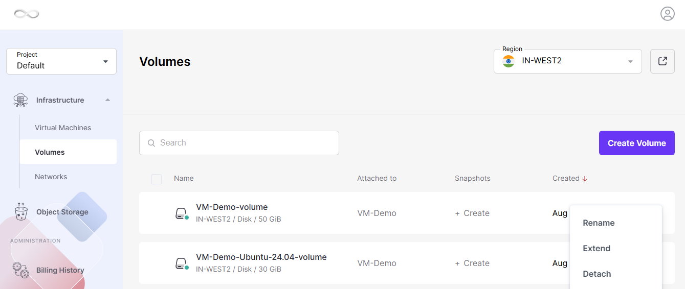
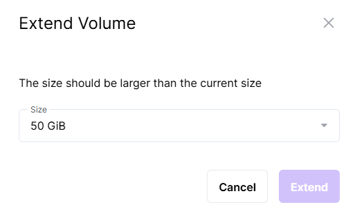
    Introduction

    Resizing volumes in CMP allows you to increase the storage capacity assigned to a virtual machine without replacing the existing volume. Volume expansion can be performed for both running and stopped virtual machines, allowing storage capacity to be increased according to workload requirements.

    Online volume resizing can be performed while the VM is running, which helps avoid downtime when additional storage capacity is required. However, increasing the volume size from the CMP dashboard does not automatically expand the partition or filesystem inside the guest operating system. Additional operating-system-level steps may therefore be required to make the newly allocated space available to applications.

    This guide explains how to extend a volume from the CMP dashboard and provides the required steps for Linux and Windows virtual machines.

    Volume Resizing

    A volume can only be increased in size. Reducing an existing volume is not supported.

    Important Notes

    • Volumes can only be extended; they cannot be shrunk.
    • Increasing the volume size from the CMP dashboard does not automatically extend the filesystem inside the guest operating system.
    • The guest operating system may require additional steps to use the newly available space.
    • Volume resizing can be performed for both running and stopped virtual machines.
    • If a volume is reverted to a snapshot that was created before the volume was extended, the increased volume size is retained.

    Extend a Volume from the CMP Dashboard

    Follow these steps to increase the size of an existing volume.

    Step 1: Log in to the CMP Dashboard

    Log in to your CMP Dashboard using your account credentials.

    Step 2: Open the Volumes Section

    Navigate to Volumes and select the volume that you want to extend.

    Step 3: Select Extend

    Click the three-dot menu associated with the volume and select Extend.

    Menu showing the Extend

    Step 4: Select the New Volume Size

    Select the required volume size and click Extend.

    Volume resize window

    Once the operation is completed, the volume is resized successfully.

    Note: Extending the volume from the CMP Dashboard increases the virtual disk capacity. The filesystem inside the VM may still need to be expanded before the operating system can use the additional space.

    Expand a Volume on a Linux Virtual Machine

    After increasing the volume size from the CMP Dashboard, additional steps may be required inside the Linux VM to make the new capacity available.

    The Linux procedure involves checking the current disk layout, extending the required partition, and resizing the filesystem.

    To know more about “How to Expand a Volume on a Linux Virtual Machine”. Click Here for more details.

    Extend a Basic Volume on a Windows VM

    On a Windows virtual machine, an existing basic volume can be extended when additional unallocated space is available on the same disk.

    To know more about “How to extend a Basic Volume on a Windows VM”. Click Here for more details.

    Conclusion

    Resizing volumes in CMP allows you to increase VM storage capacity without replacing the existing volume. The volume can be extended from the CMP Dashboard for both running and stopped VMs, helping you scale storage according to your requirements.

    After extending the volume, remember that the guest operating system may require additional steps to use the new capacity. For Linux VMs, verify the disk layout, extend the required partition, and resize the filesystem. For Windows VMs, use Disk Management to extend the volume into available adjacent unallocated space.

    Following these steps ensures that the additional storage capacity is correctly made available to the virtual machine.

    FAQ’s

    Can I decrease the size of an existing volume?

    No. Volumes can only be increased in size. Shrinking an existing volume is not supported.

    Can I resize a volume while the VM is running?

    Yes. Volume resizing supports both running and stopped virtual machines. Online resizing allows the volume capacity to be increased without stopping the VM.

    Does resizing a volume automatically increase the filesystem size?

    No. Extending the volume from the CMP Dashboard does not automatically extend the filesystem inside the guest operating system. Additional operating-system-level steps may be required.

    How do I check the disk layout on Linux?

    Use the following command:

    Bash
    lsblk

    This displays the available disks and partitions so you can identify the disk and partition that need to be extended.

    Which command is used to extend a Linux partition?

    The source procedure uses growpart. For example:

    Bash
    growpart /dev/vdb 1

    Replace the disk and partition number with the values applicable to your VM.

    Why is the new Linux storage capacity not available after extending the volume?

    Increasing the virtual disk size does not automatically increase the partition and filesystem. The partition must first be extended and the filesystem must then be resized.

    What are the requirements for extending a Windows volume?

    The unallocated space must be directly next to the volume, there must be no other volume between them, and the unallocated space must be on the same disk.

    What should I do if a newly attached Windows disk does not appear in File Explorer?

    Open Disk Management and check whether the disk is offline or unallocated. A newly attached secondary disk may need to be brought online and initialized before it can be used.

  • How to Upgrade and Downgrade CMP NVMe Storage Tiers?

    Introduction

    CMP allows you to change the storage tier of supported NVMe volumes without detaching the volume, restarting the virtual machine, or causing downtime. You can switch between Standard NVMe and Pro NVMe while the volume remains attached to a running VM.

    Storage policy changes are applied live, allowing you to increase storage performance when required or reduce storage costs when the additional performance is no longer needed.

    Supported Live Changes

    The following storage tier changes are supported:

    • Standard NVMe → Pro NVMe
    • Pro NVMe → Standard NVMe

    These changes can be performed without downtime or data loss.

    Storage Tiers

    Storage Tier Max IOPS Max Throughput Storage Architecture Live Tier Change
    Eco NVMe 15,000 500 MB/s Erasure Coding ❌ Not Supported
    Standard NVMe 25,000 1,000 MB/s 3× Replication ✅ Upgrade to Pro
    Pro NVMe 50,000 2,000 MB/s 3× Replication ✅ Downgrade to Standard

    Note: Eco NVMe uses a different storage architecture based on Erasure Coding. It cannot be converted to Standard NVMe or Pro NVMe through a live storage policy change. A new volume must be created and the data must be migrated manually.

    Before You Begin

    Before changing the storage tier, ensure that:

    • You have access to the CMP Advanced Panel.
    • The storage policy option is not available in the standard CMP Dashboard.
    • The volume can remain attached to a running VM during the storage tier change.
    • A VM reboot is not required.
    • The volume does not need to be detached.

    Access the Advanced Panel

    To access the volume storage policy:

    • Log in to the CMP Dashboard.
    • Select the appropriate region.

    Select your Region

    • Click the Advanced Panel (external link icon (↗) ) for your selected region.

    Open the Advanced Panel

    • Navigate to Volumes.

    Navigate to Volumes

    Upgrade Standard NVMe to Pro NVMe

    You can upgrade a supported Standard NVMe volume to Pro NVMe while the volume remains attached to the VM.

    Step 1: Open Volumes

    Open Volumes in the Advanced Panel.

    Navigate to Volumes in the Advanced Panel

    Step 2: Select the Volume

    Select the volume that you want to upgrade.

    The volume details panel will open.

    Click on the volume to open its detail panel

    Step 3: Edit the Storage Policy

    Locate Storage Policy under the volume properties.

    Click the Edit (Pencil) icon.

    Click the pencil icon to edit the Storage Policy

    Step 4: Select Pro NVMe

    From the storage policy drop-down menu, select:

    Pro NVMe

    Select Pro NVMe from the dropdown

    Step 5: Save the Changes

    Click Save (✓) to apply the new storage policy.

    Confirm the selection and save

    The storage policy is updated immediately.

    Verify the upgrade is applied

    Verify the upgrade is applied

    Performance after upgrade

    After upgrading to Pro NVMe, the volume supports:

    • Up to 50,000 IOPS
    • Up to 2,000 MB/s throughput
    • Zero downtime
    • No interruption to the running virtual machine

    Downgrade Pro NVMe to Standard NVMe

    You can downgrade a supported Pro NVMe volume to Standard NVMe without restarting the VM or detaching the volume.

    Step 1: Open the Volume

    Open the required volume from the Volumes section of the CMP Advanced Panel.

    Navigate to the volume in the Advanced Panel

    Step 2: Edit the Storage Policy

    Click the Edit (Pencil) icon next to Storage Policy.

    Click the pencil to open the editor

    Step 3: Select Standard NVMe

    From the storage policy drop-down menu, select:

    Standard NVMe

    Select Standard NVMe from the dropdown

    Step 4: Save the Changes

    Click Save (✓) to apply the change.

    Confirm and save the downgrade

    The volume continues operating normally while the storage policy changes.

    downgrade complete and confirmed

    Performance after downgrade

    After downgrading to Standard NVMe, the volume supports:

    • Up to 25,000 IOPS
    • Up to 1,000 MB/s throughput
    • No data loss
    • No VM restart required

    Rules & Limitations

    Supported

    The following operations are supported:

    • Live upgrade from Standard NVMe → Pro NVMe
    • Live downgrade from Pro NVMe → Standard NVMe
    • Storage policy changes while the volume is attached to a VM
    • Immediate application of the selected storage tier

    Not Supported

    The following operations are not supported:

    • Eco NVMe → Standard NVMe
    • Eco NVMe → Pro NVMe
    • Standard NVMe → Eco NVMe
    • Pro NVMe → Eco NVMe
    • Storage policy changes from the standard CMP Dashboard
    • Partial volume storage policy changes

    Important: Eco NVMe cannot be converted using a live storage policy change because it uses a different storage architecture. To move from Eco NVMe to another storage tier, a new volume must be created and the data must be migrated manually.

    Troubleshooting

    Storage Policy Option Is Not Available

    If you cannot find the Storage Policy option in the standard CMP Dashboard, open the Advanced Panel for the selected region.

    Storage policy changes are managed from the Advanced Panel and are not available from the standard CMP Dashboard.

    Pro NVMe Is Not Available as an Upgrade Option

    If Pro NVMe is not available when editing the storage policy, verify that the current volume is using Standard NVMe.

    The supported live upgrade path is:

    Standard NVMe

         ↓

    Pro NVMe

    Standard NVMe Is Not Available for Downgrade

    If Standard NVMe is not available, verify that the current volume is using Pro NVMe.

    The supported live downgrade path is:

    Pro NVMe

         ↓

    Standard NVMe

    I Want to Change an Eco NVMe Volume

    Eco NVMe does not support live conversion to Standard NVMe or Pro NVMe.

    The supported approach is to:

    1. Create a new volume with the required storage tier.
    2. Migrate the data manually.
    3. Use the new volume for the workload.

    The source documentation does not provide detailed data-migration commands, so they are not included in this KB.

    Verification Checklist

    After changing the storage tier, verify:

    • The correct volume was selected.
    • The Storage Policy was updated.
    • The required storage tier is displayed.
    • The volume remains attached to the VM.
    • The VM remains operational.
    • No reboot was required.
    • The expected storage performance tier is applied.

    Summary

    CMP supports live storage tier changes for supported NVMe volumes.

    The supported transitions are:

    Standard NVMe

         ↓

    Pro NVMe

    and:

    Pro NVMe

         ↓

    Standard NVMe

    Both operations can be performed while the volume remains attached to a running VM, without requiring a reboot or data migration.

    Eco NVMe uses a different storage architecture and cannot be converted using a live storage policy change.

    Conclusion

    CMP provides flexible NVMe storage tiers that can be changed according to workload performance and cost requirements.

    Standard NVMe can be upgraded to Pro NVMe for higher IOPS and throughput, while Pro NVMe can be downgraded to Standard NVMe when the additional performance is no longer required.

    These supported storage policy changes are applied live without detaching the volume, restarting the VM, or causing downtime. Eco NVMe requires a different migration approach because it cannot be converted through a live storage policy change.

    FAQ’s

    Can I upgrade Standard NVMe to Pro NVMe without downtime?

    Yes. Standard NVMe can be upgraded to Pro NVMe while the volume remains attached to a running VM. No reboot or downtime is required.

    Can I downgrade Pro NVMe to Standard NVMe?

    Yes. Pro NVMe can be downgraded to Standard NVMe without restarting the VM or detaching the volume.

    Can I change an Eco NVMe volume to Pro NVMe?

    No. Eco NVMe cannot be converted directly to Pro NVMe through a live storage policy change. A new volume must be created and the data migrated manually.

    Is the storage policy option available in the standard CMP Dashboard?

    No. Storage policy changes must be performed through the CMP Advanced Panel.

    Do I need to detach the volume before changing its storage tier?

    No. Supported storage tier changes can be performed while the volume remains attached to the VM.

    Do I need to restart the VM after changing the storage tier?

    No. A VM restart is not required for supported Standard NVMe and Pro NVMe tier changes.

    What is the maximum performance of Pro NVMe?

    Pro NVMe supports up to 50,000 IOPS and 2,000 MB/s throughput according to the source documentation.

    What is the maximum performance of Standard NVMe?

    Standard NVMe supports up to 25,000 IOPS and 1,000 MB/s throughput according to the source documentation.

  • Persistent Volume Expansion in Kubernetes

    1. Overview

    Kubernetes supports in-place Persistent Volume expansion, allowing you to increase the size of an existing Persistent Volume without losing existing data.

    During the expansion process:

    • Block storage is expanded at the Cloud infrastructure layer.
    • The filesystem is resized to use the newly available storage capacity.
    • Existing data remains unchanged. No data is deleted, moved, or modified.

    2. Prerequisites

    Before expanding a Persistent Volume, verify the following requirements.

    StorageClass Configuration

    The StorageClass must have volume expansion enabled:

    Bash
    allowVolumeExpansion: true

    Volume Expansion

    Only increasing the volume size is supported.

    Example:
    5Gi → 10Gi

    Shrinking an existing volume is not supported and will fail validation.

    Verify the CSI Driver

    Check that the CSI driver is running:

    Bash
    kubectl get pods -n kube-system | grep cinder

    All cinder.csi.openstack.org pods should be in the Running state.

    3. Expand the Persistent Volume

    This procedure uses YAML manifests to perform the volume expansion.

    Step 1: Update the PVC Storage Request

    Open the PersistentVolumeClaim YAML file.

    Example:
    pvc.yaml

    Update the requested storage size:

    spec:
    resources:
    requests:
    storage: 10Gi

    In this example, the volume size is increased from 5Gi to 10Gi.

    Apply the updated configuration:

    Bash
    kubectl apply -f pvc.yaml

    Step 2: Resize the Filesystem

    After the volume has been expanded, the filesystem must also be resized to use the additional capacity.

    Note: In this environment using ext4/xfs, a pod restart is required.

    If Using a Deployment

    Run:

    Bash
    kubectl rollout restart deployment <deployment-name>

    If Using a Standalone Pod

    Run:

    Bash
    kubectl apply -f pod.yml

    Kubernetes will:

    • Re-attach the expanded volume.
    • Automatically expand the filesystem when the volume is mounted.

    4. Verify the Volume Expansion

    After completing the expansion, verify that the new storage size is available.

    Check the PVC Status

    Run:

    Bash
    kubectl get pvc <pvc-name>

    Verify that:

    • The PVC status is Bound.
    • The new storage size is displayed.

    Verify the Storage Inside the Pod

    Run:

    Bash
    kubectl exec <pod-name> — df -h /data

    Check the Size column and confirm that the updated storage capacity is displayed.

    5. Safety and Recovery

    Data Integrity

    During volume expansion:

    • The expansion occurs at the end of the partition.
    • Existing data remains unchanged and safe.

    Expansion Failure

    If the expansion fails, for example because of insufficient quota:

    • The PVC status will remain Expanding.
    • The pod will continue operating with the original storage size.
    • After the issue is resolved, the expansion process will automatically continue.

    Best Practice

    • Perform Persistent Volume expansion during a low-traffic period.
    • This helps reduce the impact of any required pod restarts.

    6. Summary

    Kubernetes supports safe, in-place Persistent Volume expansion without affecting existing data.

    The expansion process requires:

    • A StorageClass with volume expansion enabled.
    • Updating the requested storage size in the YAML file.
    • Restarting the pod.
    • Verifying the new storage size after expansion.